PART 4
ENGINE/DC CONTROL
Page 104
Section 4.3
Operational Analysis
TRANSFER TO STANDBY
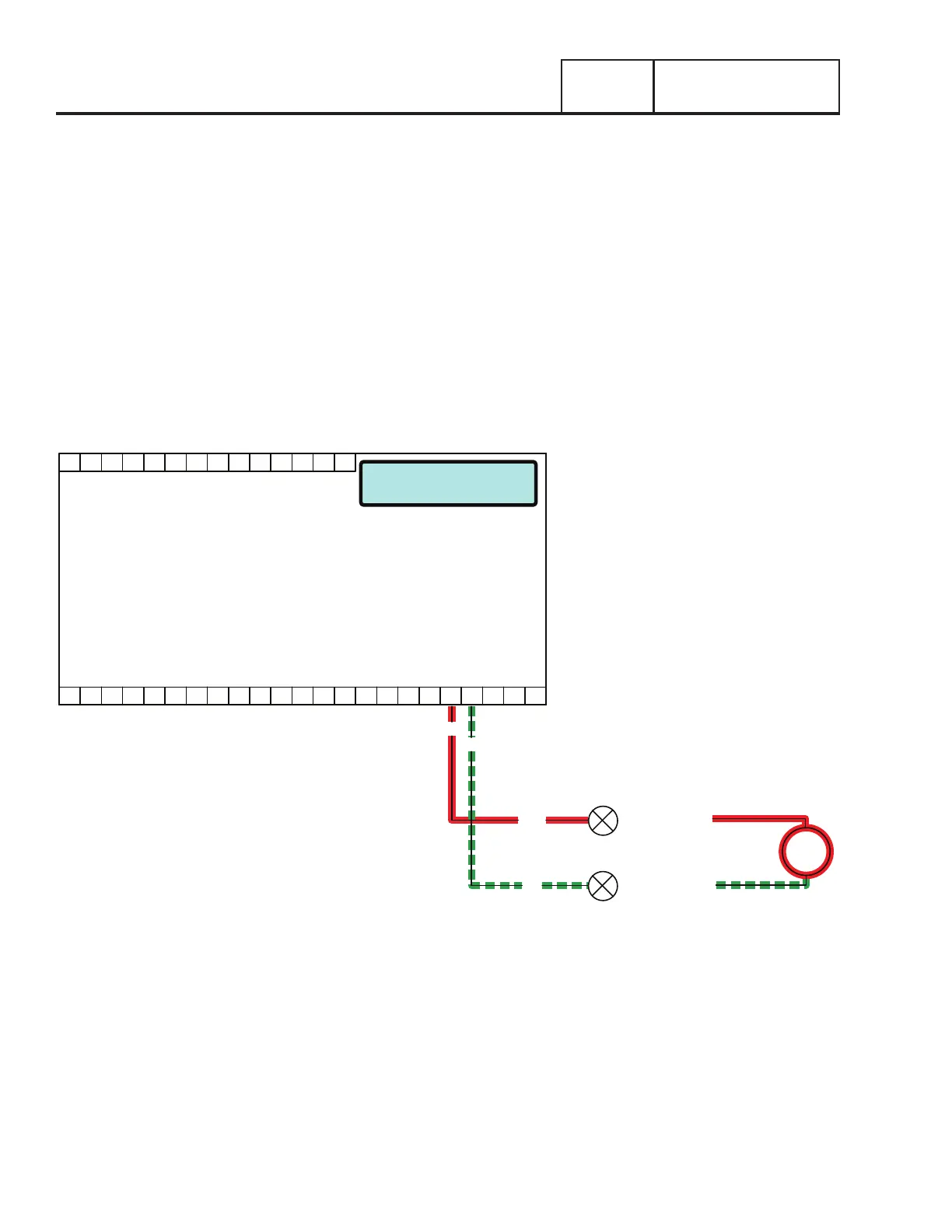
In Figure 102 the Generator is running, the controllers “engine warm-up” timer has expired and generator AC output is available
to the transfer switch Terminal Lugs E1 and E2 and to the open contacts on the transfer relay. Transfer to Standby may be briefly
described as follows:
•12 VDC is delivered to the transfer relay coil (TR1 - Terminal A) via Wire 194. The 12 VDC circuit is completed back to the
controller via Wire 23 (TR1 - Terminal B). However, the controller’s logic holds Wire 23 open from ground and the TR1 relay is
de-energized.
•When the “engine warm-up timer” expires, the controller will take Wire 23 to ground. The TR1 relay energizes and its normally
open contacts close (standby position).
•Generator voltage is now delivered to the standby closing coil (C2), via Wire E1 and E2, the now closed TR1 contacts, Wire 205,
the limit switch (SW3), Wire B, and a bridge rectifier. The standby closing coil energizes and the main current carrying contacts
of the transfer switch are actuated to the “Standby” position.
•As the main contacts move to the “Standby” position, a mechanical interlock actuates SW3 to its open position and limit switch
(SW2) to the “Utility” position. When SW3 opens the C2 coil de-energizes.
•Generator voltage is now available to the LOAD terminals (T1 and T2) of the transfer switch.
Running - Utility Loss
PRINTED CIRCUIT BOARD
CONTROLLER
J4
18171615141312109 1186 721 43 5 2322212019
141312109 1186 721 43 5
TRANSFER
+ BATTERY
23
194
194
23
TR1
Figure 101.

 Loading...


