SYSTEM CONTROL INTERCONNECTIONS
The system control wiring when properly connected monitors
Utility source voltage for drop out below a preset value. When
voltage drops below a preset level, the Generator will start
in automatic and transfer electrical Loads to the “Standby”
position. On restoration of Utility source voltage above a
preset value, retransfer of electrical loads from the “Standby”
position to the “Utility” position will occur and the Generator
will shutdown.
The transfer switch and the Generator will both have a terminal
strip labeled “Customer Connections.” The connections are
as follows:
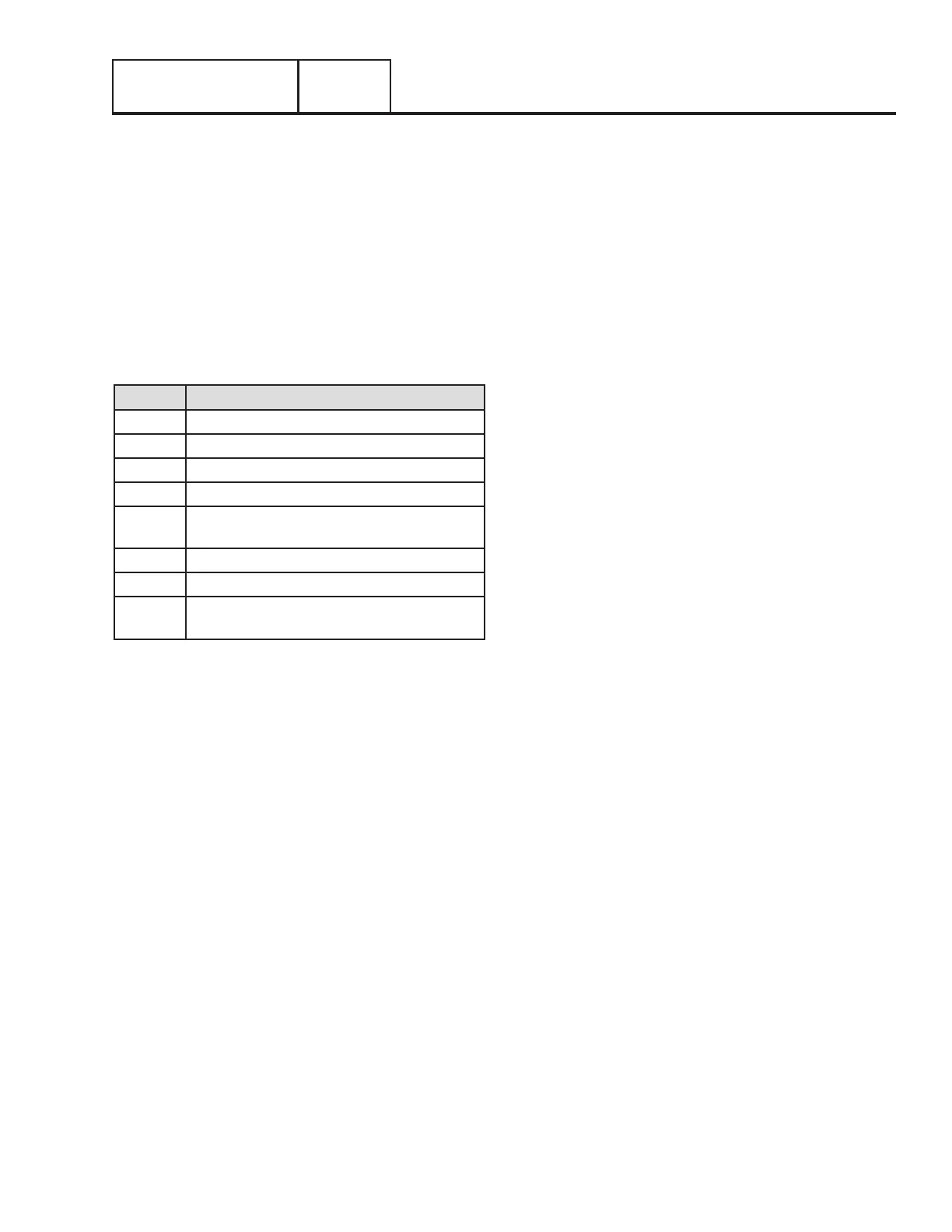
Table 1. Typical Control Wiring Connections
Wire # Purpose
194 Provides 12VDC to the transfer relay
23 Switched to ground for transfer relay operation
N1 240VAC sensing for the controller
N2 240VAC sensing for the controller
T1 Provides 120VAC from Load side of the
CONTACTOR for battery charging
209 Connects to 210 for an alarm
210 Connects to 209 for an alarm
0 Provides a DC common for Nexus Smart
Switches
GENERAL INFORMATION
PART 1
Page 15
Section 1.2
Installation Basics

 Loading...


