TRANSFER SWITCH
PART 3
Page 63
Control 194, 23
Wire 194 and 23 provide control of the transfer relay by the
controller. Wire 194 provides continuous DC voltage to the
transfer switch. Wire 23 is held open from ground by the
controller’s logic until a Utility failure is “sensed”.
FUSE HOLDER
The fuse holder holds three fuses, designated as fuses F1, F2,
and F3.
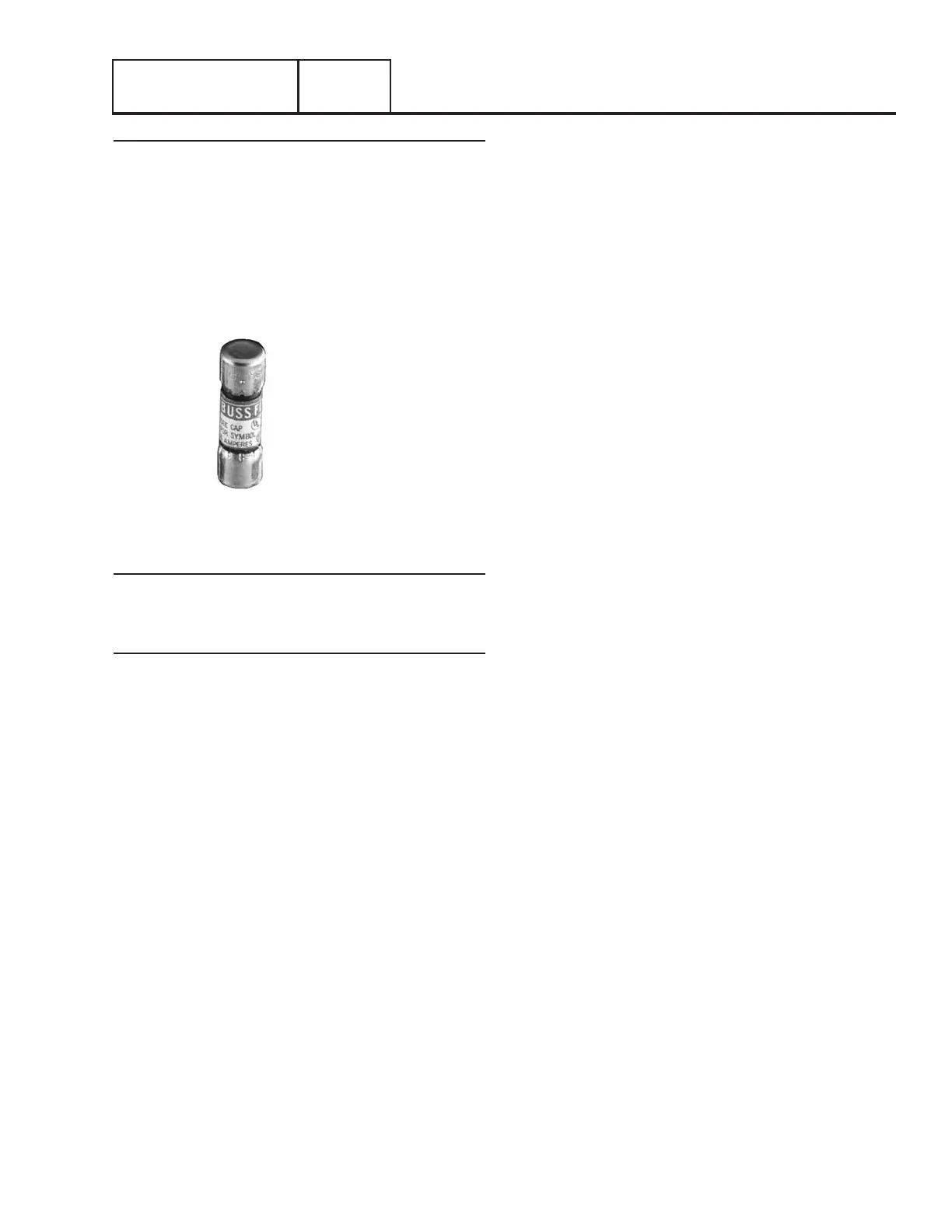
5 AMP 600V RATING
FAST ACTING
BUSSMANN PART# BBS-5
Figure 65. Fuse
Fuses F1, F2
These two fuses protects the N1 and N2 circuit against
overload
Fuse F3
This fuse protects the battery charger against overload.
Section 3.1
Description and Components

 Loading...


