AC GENERATORS
PART 2
Page 43
STATOR
ROTOR
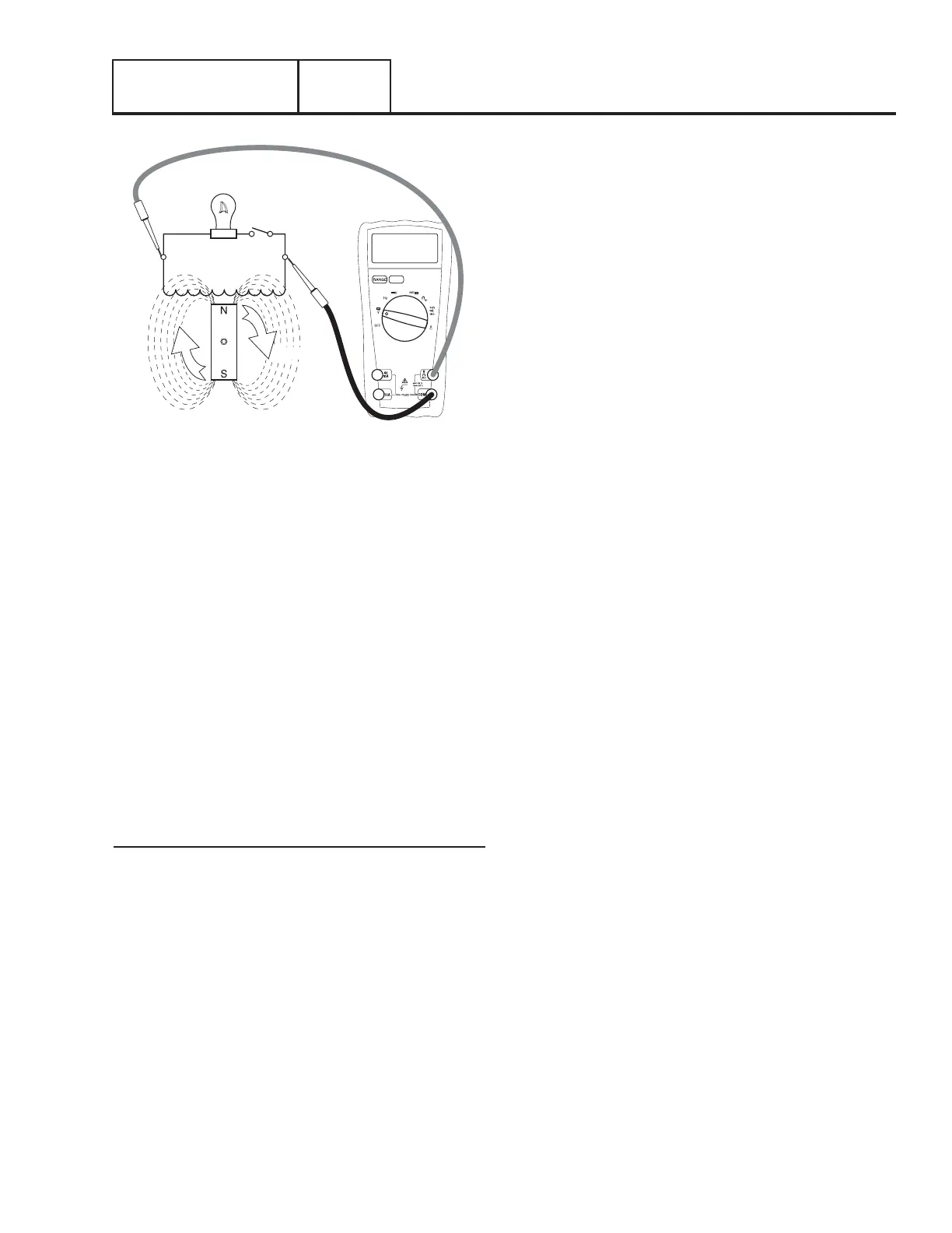
MAGNETIC FIELD
200 VAC
Figure 45. Increased Excitation Voltage = Increased Magnetic
Lines of Flux = Increased AC Output Voltage.
The regulated excitation from the regulator is delivered to the
rotor windings through Wire 4 and the positive brush and slip
ring. This results in current flowing through the field windings
to the negative slip ring and brush, and then to ground.
The greater the current flow through the windings the more
concentrated the lines of flux around the rotor become. The
more concentrated the lines of flux around the rotor, which cut
across the stationary stator windings, the greater the voltage
induced into the stator. Refer to Figures 44 and 45
Initially, the AC power windings output voltage “sensed” by
the AVR is low. The AVR reacts by increasing the excitation
voltage (and hence current flow) to the rotor until AC output
voltage increases to a preset level. The AVR then maintains the
voltage at this level. For example, if voltage exceeds the desired
level, the AVR will decrease excitation. Conversely, if voltage
drops below the desired level, the AVR responds by increasing
excitation.
AC Power Winding Output
When electrical loads are connected across the AC power
windings to complete the circuit, current flows through the
circuit powering the loads.
As load changes this will result in a corresponding change in
voltage; as load demand increases the voltage will tend to drop;
as load demand decreases the voltage will tend to increase.
The AVR changes excitation to provide a constant output
voltage with minimal increase or decrease during load changes.
Frequency is also affected during load changes. However,
frequency is a function of rotor speed (engine RPM); the engine
electronic governor (integral to the control panel) will respond
to any engine speed changes to maintain a stable, isochronous,
frequency output of 60Hz.
The Automatic Voltage Regulator and the Electronic Governor
work together to provide output voltage regulation of +/- 1%
voltage regulation and +/- 0.25% steady state, isochronous,
frequency (speed) regulation.
Section 2.2
Operational Analysis

 Loading...


