AutoVu SharpX mobile installation
tip.genetec.com | AutoVu Hardware Guide for SharpX Mobile Installation
EN.410.018-XS(6) | Last updated: October 6, 2016 10
Connecting SharpX systems in a test environment
To verify that everything is working properly before installing your SharpX system in the field, you
can power up and connect the system in a lab or similar test environment.
What you should know
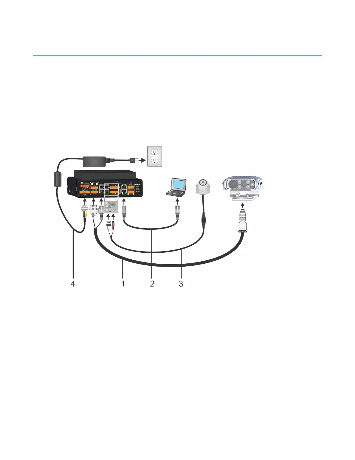
Cables and a power supply are provided.
The image below depicts a SharpX mobile setup using the Genetec lab cable (part number AU-
KLABPWRKIT for Sharp or AU-K-LABPWRKITX for SharpX). For more information on the available lab
cables, contact your Genetec Sales Representative.
To connect the SharpX, refer to the illustration below, and the steps that follow:
1 Connect the SharpX cable to the SharpX and connect the power and network cables to the LPR
Processing Unit.
2 Plug the network cable from the LAN1 port of the LPR Processing unit to the computer.
3 (Optional) Connect the wheel imaging camera's BNC and power to the LPR Processing Unit via the
Tire/Aux Imaging Adapter Module.
4 Connect the 24 VDC power supply to the LPR Processing Unit's power port and supply power.
You are ready to test the SharpX camera. If you have a wheel imaging camera, you can test that too.