AutoVu SharpX mobile installation
tip.genetec.com | AutoVu Hardware Guide for SharpX Mobile Installation
EN.410.018-XS(6) | Last updated: October 6, 2016 35
6 Connect the LPR Processing Unit to the vehicle’s power and ignition signals.
7 Connect the camera cable to the SharpX camera unit.
8 (Optional) If the installation includes wheel imaging cameras that require a BNC connection, you
will need to install the Tire/Aux Imaging Adapter Module.
The SharpX is connected and ready to be configured.
NOTE:
Related Topics
Hardware components for SharpX mobile installation on page 2
Connecting the power port to the LPR Processing Unit
To power the SharpX cameras, you must connect the power port to the LPR Processing Unit.
What you should know
As a best practice, use a red wire for power (+) and a black wire for ground (GND) to be consistent
with similar Genetec installations.
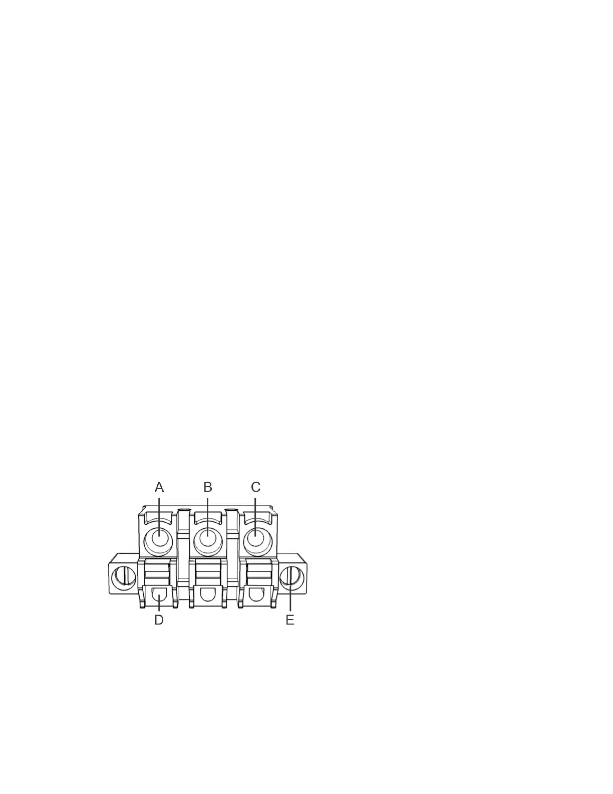
To connect the power port:
1 Plug the 3-pole connector into the power port, and then tighten the securing screws.
2 Strip 10 mm (3/8 in.) of insulation from your stranded copper wires.
BEST PRACTICE: For a more secure connection, crimp a ferrule to the tip of each stripped wire.
Ensure that you use the appropriate ferrule for the wire gauge.
WARNING: Do not lengthen any power or signal wires. If the wire you are installing is too short,
replace with a new longer wire. Splices are a point of possible failure, causing the system to
malfunction.
3 Insert the wires into the connector poles.
• A: Permanent 12V (+). Use 14 AWG (red).
• B: Negative/Return/GND. Use 14 AWG (black).
• C: 12V Ignition (IGN). Use 20 AWG to 14 AWG (yellow). Include a 0.5A fuse (in-line or in the OEM
fuse box using a tap fuse adapter).
• D: Tension clamps