Omnia Maintenance Through USB Omnia PCB
MDE-5369E FlexPay™ IV (with Omnia) Programming and Service Manual · April 2020 Page 5-53
LEDs Glowing Sequence
This section provides information about sequence in which the LEDs on Omnia board glow
and its significance. The sequence in which LEDs glow signify different USB Maintenance
operations.
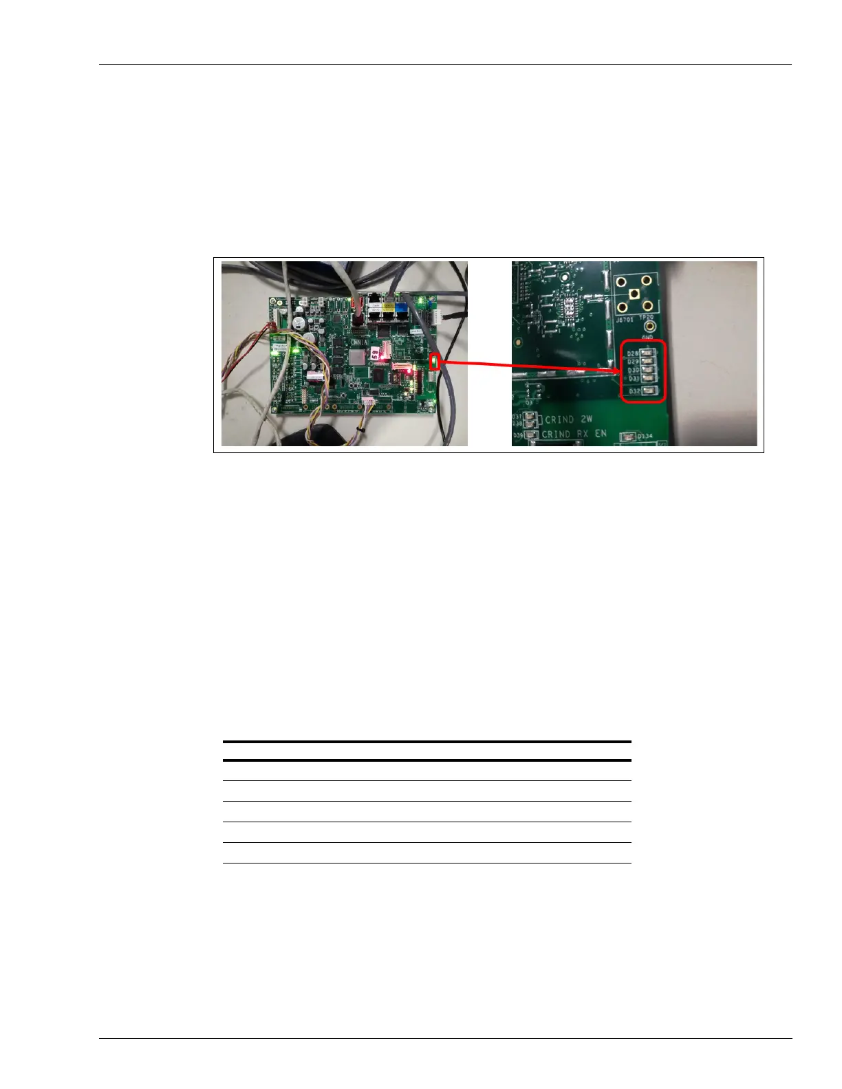
Figure 5-77: LEDs (from D28 to D32)
The following are the LEDs involved:
D32 (Red)
• Solid Red: Indicates that maintenance operation in progress.
• Blink
ing: Indicates that Error on USB/JSON format or Error on operation.
• Off: Indica
tes that maintenance completed with No Errors.
Note: DO NOT REMOV
E USB drive when Solid Red Status.
D31 to D28 (Green)
• Slow Blinking: Indicates that related operation in Progress.
• Fast
Blinking: Indicates that related operation completed with Error.
• Solid Gr
een: Indicates that related operation completed with Success.
LED Operation
D28 Reboot
D29 Retrieve Configuration/Reset Network
D30 Log Retrieval
D31 Packages Installation
D32 Maintenance In Progress/Formal Checks/Final Result
 Loading...