GKB 4CH/8CH VFire Server
11
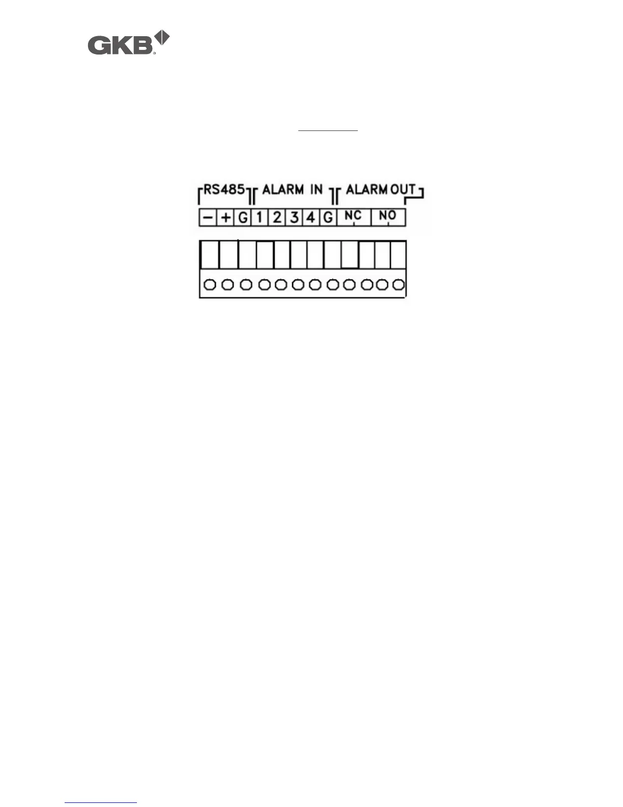
7. RS-485 Connector
Connect this connector to RS-485 compatible PTZ camera(s) or keyboard.
Please refer to the manuals come with the RS-485 compatible devices for the
correct settings. Please refer to Appendix C for the Keyboard Control Protocol
for the network video recorder.
8. Alarm Input Connectors (ALARM IN 1-4)
Connect these connectors to external devices such as sensors or door
switches.
9. Alarm Output Connectors (ALARM OUT NC(1)/NO(2))
Connect NC connectors (left) to Normally Closed (NC) alarm output, or NO
connectors (right) to Normally Open (NO) alarm output. Please note that only
one of the NC or NO connectors can be connected only.
10. Power Cord Inlet (DC 12V)
Connect to DC +12V power source.
11. PoE Ethernet Connectors (optional)
Connect these connectors to PoE IP-CAM, +48V will be output to IP-CAM.
12. IP-CAM Ethernet Connectors (optional)
Connect these connectors to IP-CAM.
13. Ethernet Connector (optional)
Connect this unit to a 10/100Base-T Ethernet network through this port instead
of the Ethernet connector mentioned in item 5.
14. Power Cord Inlet (DC 48V, optional)
Connect to DC +48V power source. DC +48V is used for PoE module.