EasyManuals Logo

GMI PS241 User Manual

GMI PS241
92 pages
To Next Page IconTo Next Page
To Previous Page IconTo Previous Page
Page #33 background imageLoading...
Page #33 background image
2-13
OPERATION
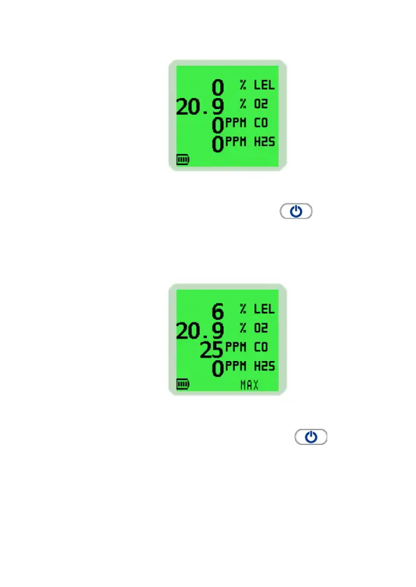
Fig. 2-17 Normal Operating Display
Press the Right Hand (RH) button again, while
the screen light is ON, to view the maximum gas values
stored in the instrument.
The example in Fig. 2-18 illustrates the maximum (MAX)
gas values stored in a 4-gas instrument.
Fig. 2-18 Maximum Gas Values
2. Press the Right Hand (RH) button again to
view the minimum gas values stored in the instrument.
Note: This screen is only displayed when an Oxygen
sensor is tted in the instrument.

Table of Contents

Questions and Answers:

Question and Answer IconNeed help?

Do you have a question about the GMI PS241 and is the answer not in the manual?

GMI PS241 Specifications

General IconGeneral
TypePressure Switch
Protection ClassIP65
Power Supply24 VDC
Contact TypeSPDT
Process ConnectionG1/4"
Operating Temperature-20...80°C

Related product manuals