Page 31 of 49 S1024.mz-32-V2.1-EN
receiver). Touching the check mark in the bottom right confirms the
selection.
7. If necessary, proceed identically with other receiver connections.
8. By tapping on the symbol pulse , you can change to level and
back to pulse again.
When the symbol pulse is selected, servo pulses are output to the
corresponding channel output.
When the symbol level is selected, the output of the corresponding
channel is switched to high or low.
Notes
• Switching to level allows the direct connection of transistors or
LEDs to the receiver output via a series resistor.
• For Graupner receivers GR-12 (#33506), GR-16 (#33508), GR-24
(#33512), GR-32 (#33516) and GR-24 PRO (#33583) as well as
GR-16L (#S1021), GR-24L (#S1022) and GR-32L (#S1023) series
resistors are already installed and LEDs can be connected directly
between the orange servo pulse wire and the brown or black “-”
wire.
9. Touching “OK” completes the process. Touching “Reset” resets the
receiver to the default settings.
In both cases, the display will close, and you will return to the “RF Set” menu.
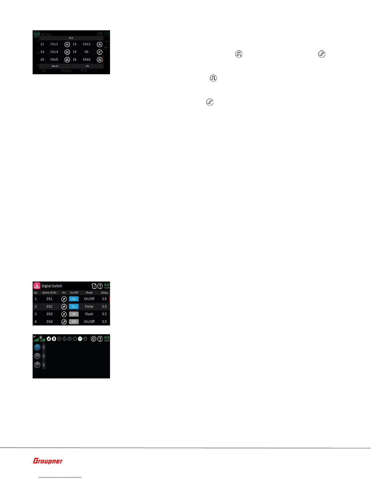
Assign Digital Switches to Widgets
1. Switch to the submenu “Digital Switch”.
2. Tap on the first “Act” icon to activate the Digital Switch and select
the desired mode (On/Off, Pulse or Flash).
3. Connect for example a servo to the channel you designated as Digital
Switch.
4. Go to the Home page and select an empty deck or available block
and bring up the Widget Editor.
5. Select the “Digital Switch” widget and tap on DS1 which is the digital
channel we assigned in the previous step.
6. Test the operation by tapping on the button. You can change its
behavior in the “Digital Switch” submenu.
 Loading...