EN - 28
• Model 997001 only (side-discharge):
Turn hex bolts counter-clockwise to
loosen. Remove hardware, blades, and
lower spindle guard. Sharpen or
discard blades and retain hardware and
lower spindle guard.
• Model 997002 only (rear-discharge): To
loosen, turn hex bolts counter-
clockwise for left and center blades and
clockwise for right blade. Remove
hardware, blades, and lower spindle
guard. Sharpen or discard blades and
retain hardware and lower spindle
guard.
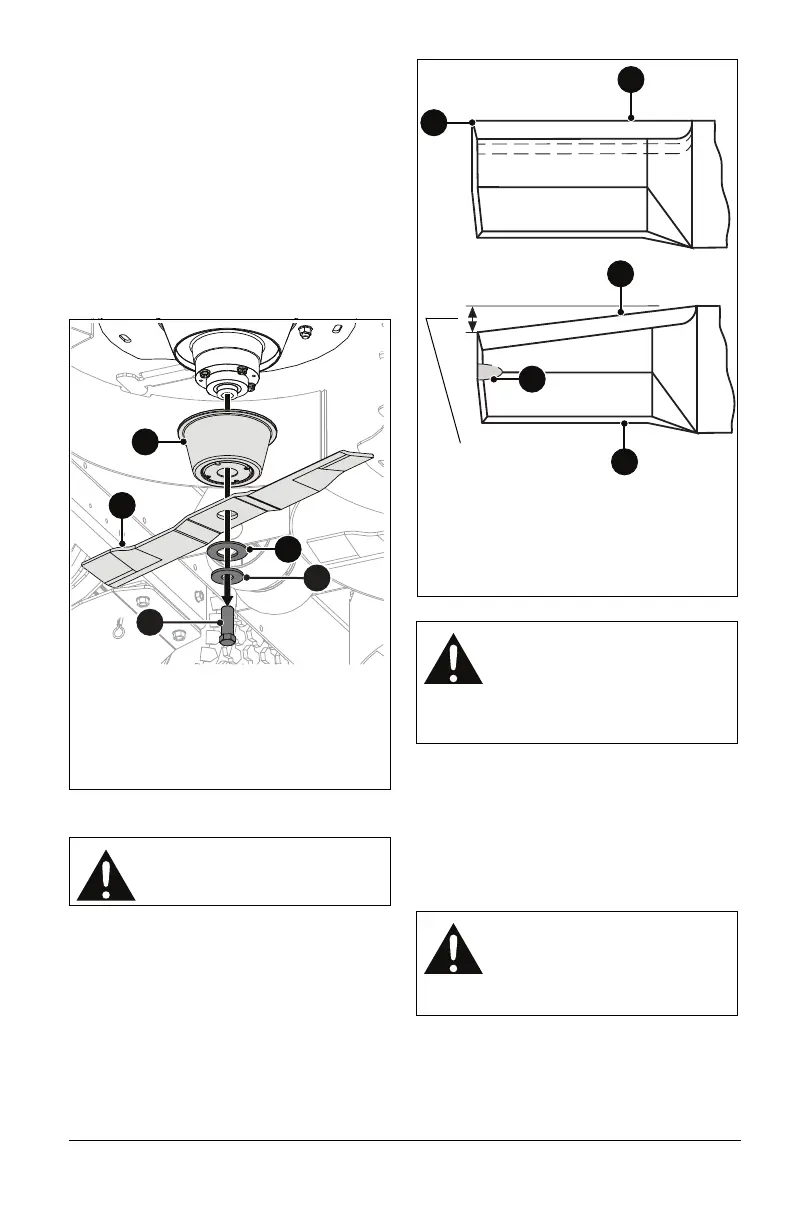
Sharpen Blades
1. Remove blades. Discard blades if:
• More than 1.3 cm (1/2") of metal is
removed.
• Air lifts are eroded.
• Blades are bent or broken.
2. File or grind an equal amount of metal
from each cutting edge of the blade until
sharp. DO NOT change angle of cutting
edge or round the corner of the blade.
See Figure 29.
3. Check blade balance by sliding an
unthreaded bolt through center hole. Hold
the bolt level. If blade does not remain
horizontal, sharpen the heavy end until
blade is balanced.
Install Blades
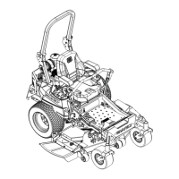
See Figure 28.
1. Secure lower spindle guards and blades
to spindles using hardware removed
earlier.
• Model 997001 only: Turn hex bolts
clockwise to tighten.
CAUTION: DO NOT sharpen
blades while attached to unit.
Figure 28
1. Hex Bolt
2. Flat Washer
3. Belleville Washer
4. Mower Blade
5. Lower Spindle Guard
5
4
1
3
2
CAUTION: Unbalanced blades
cause excessive vibration and
eventual damage to unit.
Balance blades before
reinstalling on unit. NEVER weld
or straighten blades.
CAUTION: Mating surfaces
between spindle, lower spindle
guard, blade and washer MUST
be free of debris to ensure
correct tightness and alignment.
Figure 29
DO NOT sharpen to this
pattern.
Sharpen to this pattern.
1. Cutting Edge
2. Square Corner
3. Air Lift Erosion
4. Air Lift
DISCARD if more than
1.3 cm (1/2")
1
1
2
4
3