EasyManuals Logo

Grimm Mini-LAS 11-R User Manual

Default Icon
83 pages
To Next Page IconTo Next Page
To Previous Page IconTo Previous Page
Page #17 background imageLoading...
Page #17 background image
Model 11-R
GRIMM AEROSOL TECHNIK GmbH & Co.KG Seite 17 von 83
2 Device description
Only put the device into operation after reading this manual!
2.1 Connections on the Mini-LAS 11-R
The section that follows explains the various control elements of your dust monitor. In operating the
device, one differentiates between standby mode and operating mode. All settings can be read and
changed. In operating mode, the device and all settings are fixed and cannot be changed.
2.1.1 Connections on the cover, front and right side panel
1
Display
6
Membrane keyboard
2
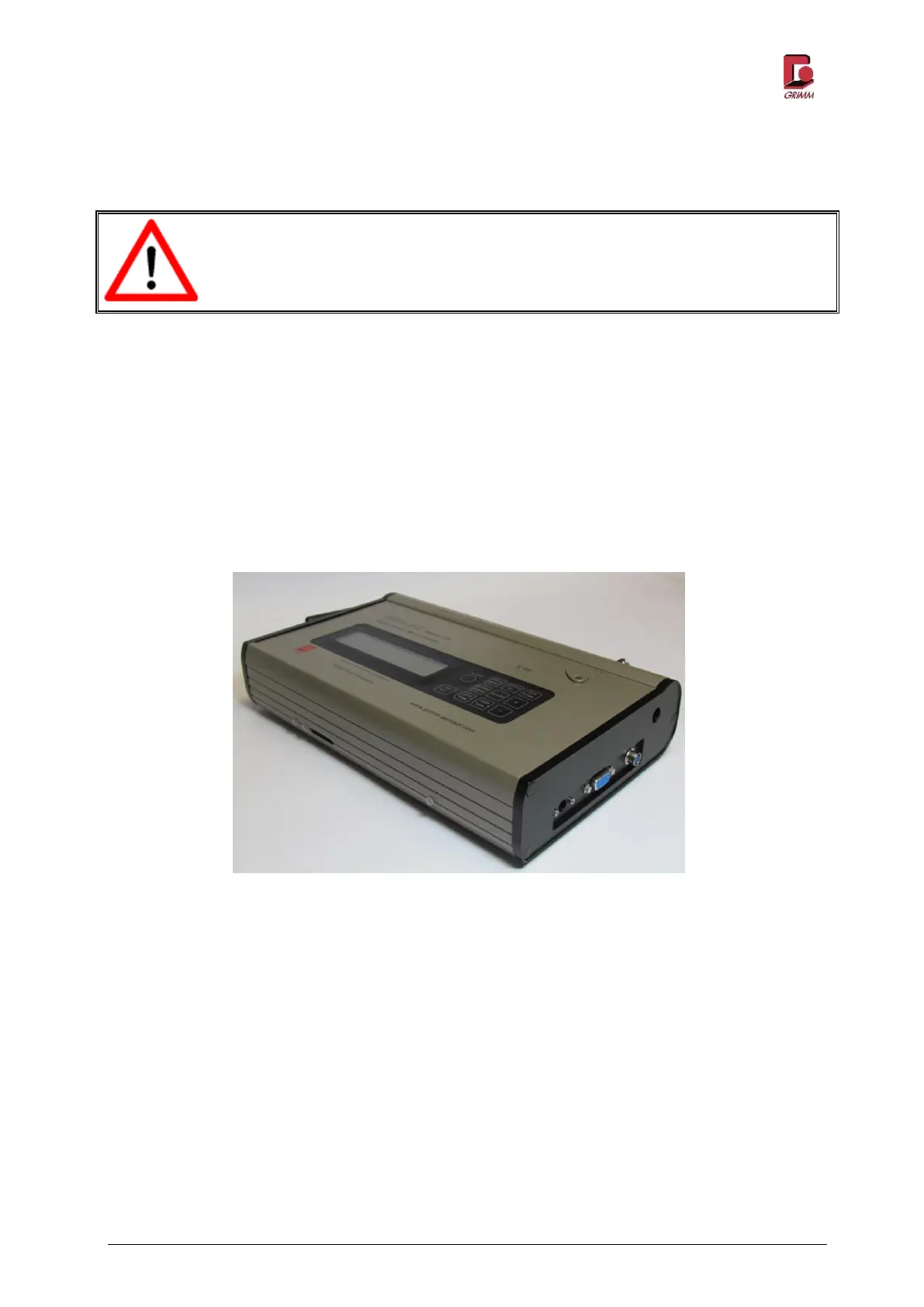
Operational readiness LED
7
Sample intake (closed)
3
Memory card LED
8
Analogue jack
4
Memory card slot
9
RS-232 interface
5
Status LED
10
Mains charger connection
1
3
4
2
4
5
6
8
Figure 2-1: Control elements on the cover, front and right side panel of the
Mini-LAS 11-R
1
2
3
5
6
7
9
10
4
8

Table of Contents

Questions and Answers:

Question and Answer IconNeed help?

Do you have a question about the Grimm Mini-LAS 11-R and is the answer not in the manual?

Grimm Mini-LAS 11-R Specifications

General IconGeneral
BrandGrimm
ModelMini-LAS 11-R
CategoryMeasuring Instruments
LanguageEnglish