16
Fig. 34 Terminals for relay connection, B3
Fig. 35 Terminals for relay connection, B4
Fig. 36 Terminals for relay connection, C3 and C4, in the
upper right corner of the CUE
6.5 Connecting the MCB 114 sensor input module
The MCB 114 is an option offering additional analog inputs for the
CUE.
6.5.1 Configuration of the MCB 114
The MCB 114 is equipped with three analog inputs for these
sensors:
• One additional sensor 0/4-20 mA.
See section 10.7.13 Sensor 2 (3.16).
• Two Pt100/Pt1000 temperature sensors for measurement of
motor bearing temperature or an alternative temperature, such
as liquid temperature. See sections 10.7.18 Temperature
sensor 1 (3.21) and 10.7.19 Temperature sensor 2 (3.22).
When the MCB 114 has been installed, the CUE will automatically
detect if the sensor is Pt100 or Pt1000 when it is switched on.
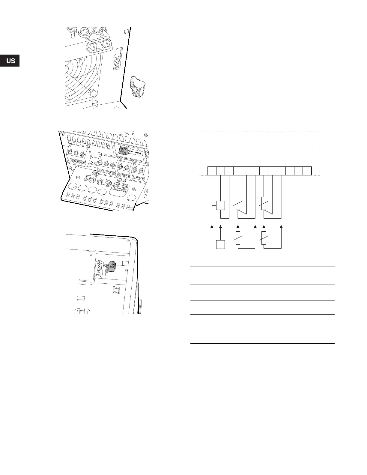
6.5.2 Wiring diagram, MCB 114
Fig. 37 Wiring diagram, MCB 114
Terminals 10, 11 and 12 are not used.
TM03 9442 4007TM03 9441 4007TM03 9440 4007
TM04 3273 3908
Terminal Type Function
1 (VDO) +24 V out Supply to sensor
2 (I IN) AI 3 Sensor 2, 0/4-20 mA
3 (GND) GND Ground for analog input
4 (TEMP)
5 (WIRE)
AI 4 Temperature sensor 1, Pt100/Pt1000
6 (GND) GND Ground for temperature sensor 1
7 (TEMP)
8 (WIRE)
AI 5 Temperature sensor 2, Pt100/Pt1000
9 (GND) GND Ground for temperature sensor 2
1 98765432
1
2
1
1
1
0
VDO
I IN
GND
TEMP
WIRE
GND
TEMP
WIRE
GND
+
-
+
Grundfos.bk Page 16 Friday, July 30, 2010 10:10 PM
 Loading...


