13
6.3 Connecting the signal terminals
Connect the signal cables according to the guidelines for good
practice to ensure EMC-correct installation. See section
6.6 EMC-correct installation.
• Use screened signal cables with a conductor gauge size of
min. 22 AWG and max. 16 AWG.
• Use a 3-conductor screened bus cable in new systems.
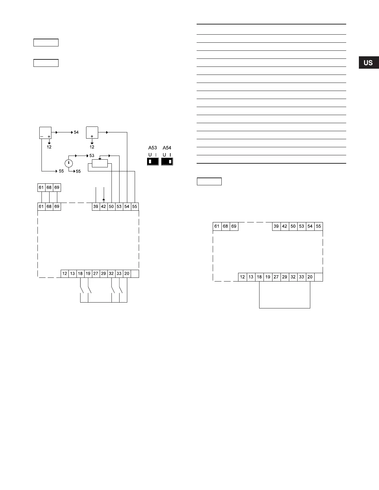
6.3.1 Wiring diagram, signal terminals
Fig. 21 Wiring diagram, signal terminals
Terminals 27, 29 and 37 are not used.
6.3.2 Minimum connection, signal terminals
Operation is only possible when the terminals 18 and 20 are
connected, for instance by means of an external on/off switch or
ashort wire.
Fig. 22 Required minimum connection, signal terminals
As a precaution, signal cables must be separated
from other groups by reinforced insulation in
their entire lengths.
If no external on/off switch is connected, short-
circuit terminals 18 and 20 using a short wire.
TM03 8800 2507
+24 V out
+24 V out
DI 2
DI 3
DI 4
GND
GND
AO 1
+10 V out
Ext. setpoint
Sensor 1
GND
RS-485 GND Y
RS-485 A
RS-485 B
0/4-20 mA
1 K
0-20 mA
0/4-20 mA
0-10 V0-10 V
Start/stop
Terminals
53 and 54:
See section
6.3.5
Terminal Type Function
12 +24 V out Supply to sensor
13 +24 V out Additional supply
18 DI 1 Digital input, start/stop
19 DI 2 Digital input, programmable
20 GND Ground for digital inputs
32 DI 3 Digital input, programmable
33 DI 4 Digital input, programmable
39 GND Ground for analog output
42 AO 1 Analog output, 0-20 mA
50 +10 V out Supply to potentiometer
53 AI 1 External setpoint, 0-10 V/0/4-20 mA
54 AI 2 Sensor input, sensor 1, 0/4-20 mA
55 GND Ground for analog inputs
61 RS-485 GND Y GENIbus, GND
68 RS-485 A GENIbus, signal A (+)
69 RS-485 B GENIbus, signal B (-)
The RS-485 screen must be connected to ground.
TM03 9057 3207
Grundfos.bk Page 13 Friday, July 30, 2010 10:10 PM
 Loading...


