15
The reference potential, GND, for RS-485 (Y) communication
must be connected to terminal 61.
If more than one CUE unit is connected to a GENIbus network,
the termination contact of the last CUE must be set to "ON"
(termination of the RS-485 port).
The factory setting of the termination contact is "OFF"
(not terminated).
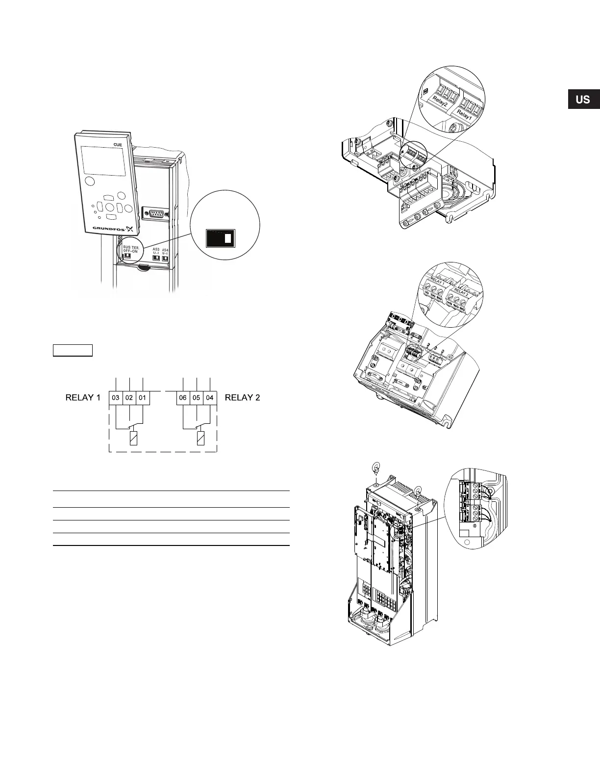
Remove the control panel to set the contact. See fig. 29.
Fig. 29 Setting the termination contact to "ON"
6.4 Connecting the signal relays
Fig. 30 Terminals for signal relays in normal state
(not activated)
Access to signal relays
The relay outputs are positioned as shown in figs 31 to 36.
Fig. 31 Terminals for relay connection, A2 and A3
Fig. 32 Terminals for relay connection, A5, B1 and B2
Fig. 33 Terminals for relay connection, C1 and C2
TM03 9006 2807
As a precaution, signal cables must be separated
from other groups by reinforced insulation in
their entire lengths.
TM03 8801 2507
Terminal Function
C 1C 2Common
NO 1 NO 2 Normally open contact
NC 1 NC 2 Normally closed contact
TM03 9007 2807TM03 9008 2807TM03 9009 2807
Grundfos.bk Page 15 Friday, July 30, 2010 10:10 PM
 Loading...


