38
Replaced
When the warning Replace motor bearings has been confirmed,
• the counter is set to 0.
• the number of relubrications is set to 0.
• the number of bearing changes is increased by 1.
10.7.18 Temperature sensor 1 (3.21)
This display is only shown if an MCB 114 sensor input module
has been installed.
Select the function of a Pt100/Pt1000 temperature sensor 1
connected to an MCB 114:
• D-end bearing
• ND-end bearing
• Other liq. temp. 1
• Other liq. temp. 2
• Motor winding
• Pumped liq. temp.
• Ambient temp.
• Not active.
10.7.19 Temperature sensor 2 (3.22)
This display is only shown if an MCB 114 sensor input module
has been installed.
Select the function of a Pt100/Pt1000 temperature sensor 2
connected to an MCB 114:
• D-end bearing
• ND-end bearing
• Other liq. temp. 1
• Other liq. temp. 2
• Motor winding
• Pumped liq. temp.
• Ambient temp.
• Not active.
10.7.20 Standstill heating (3.23)
The standstill heating function can be set to these values:
• Active
• Not active.
When the function is set to Active and the pump is stopped by a
stop command, a current will be applied to the motor windings.
The standstill heating function pre-heats the motor to avoid
condensation.
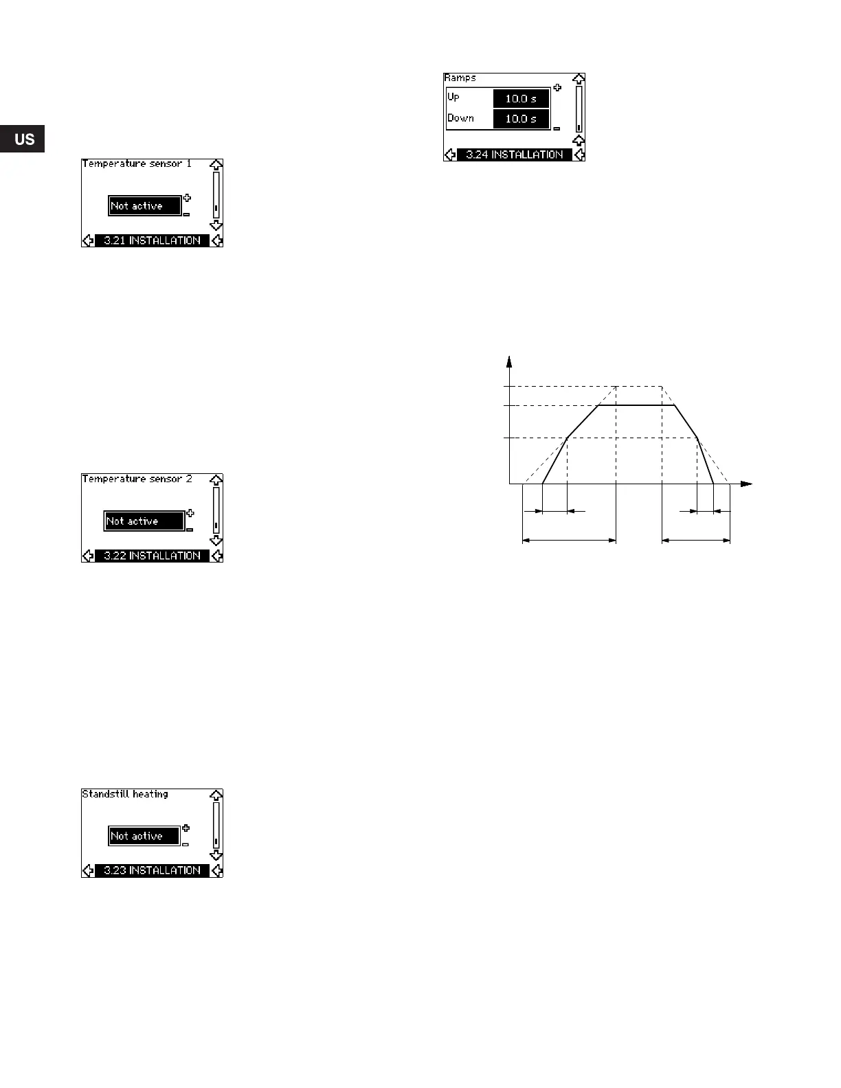
10.7.21 Ramps (3.24)
Set the time for each of the two ramps, ramp-up and ramp-down:
• Factory setting:
Depending on power size.
• The range of the ramp parameter:
1-3600 s.
The ramp-up time is the acceleration time from 0 rpm to the rated
motor speed. Choose a ramp-up time such that the output current
does not exceed the maximum current limit for the CUE.
The ramp-down time is the deceleration time from rated motor
speed to 0 rpm. Choose a ramp-down time such that no
overvoltage arises and such that the generated current does not
exceed the maximum current limit for the CUE.
Fig. 55 Ramp-up and ramp-down, display 3.24
11. Setting by means of PC Tool E-products
Special setup requirements differing from the settings available
via the CUE require the use of Grundfos PC Tool E-products. This
again requires the assistance of a Grundfos service technician or
engineer. Contact your local Grundfos company for more
information.
TM03 9439 0908
Rated
Ramp-up Ramp-down
Speed
Time
Minimum
Initial ramp Final ramp
Maximum
Grundfos.bk Page 38 Friday, July 30, 2010 10:10 PM
 Loading...


