33
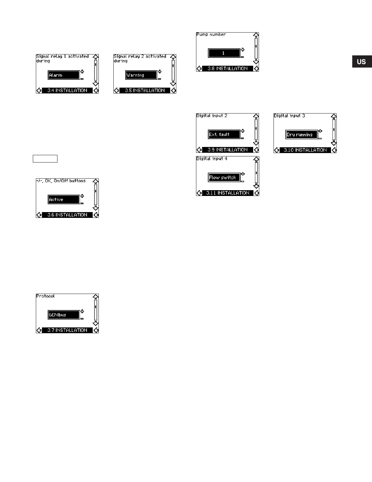
10.7.4 Signal relays 1 and 2 (3.4 and 3.5)
The CUE has two signal relays. In the display below, select in
which operating situations the signal relay should be activated.
10.7.5 Buttons on the CUE (3.6)
The editing buttons (+, –, On/Off, OK) on the control panel can be
set to these values:
• Active
• Not active.
When set to Not active (locked), the editing buttons do not
function. Set the buttons to Not active if the pump should be
controlled via an external control system.
Activate the buttons by pressing the arrow up and arrow down
buttons simultaneously for 3 seconds.
10.7.6 Protocol (3.7)
This display shows the protocol selection for the RS-485 port of
the CUE. The protocol can be set to these values:
• GENIbus
•FC
•FC MC.
If GENIbus is selected, the communication is set according to the
Grundfos GENIbus standard. FC and FC MC is for service
purpose only.
10.7.7 Pump number (3.8)
This display shows the GENIbus number. A number between 1
and 199 can be allocated to the pump. In the case of bus
communication, a number must be allocated to each pump.
The factory setting is "–".
10.7.8 Digital inputs 2, 3 and 4 (3.9 to 3.11)
The digital inputs of the CUE (terminal 19, 32 and 33) can
individually be set to different functions.
Select one of the following functions:
• Min. (min. curve)
• Max. (max. curve)
• Ext. fault (external fault)
• Flow switch
• Alarm reset
• Dry running (from external sensor)
• Accumulated flow (pulse flow, only terminal 33)
• Not active.
The selected function is active when the digital input is activated
(closed contact). See also section 13.1 Digital inputs.
Min.
When the input is activated, the pump will operate according to
the min. curve.
Max.
When the input is activated, the pump will operate according to
the max. curve.
Ext. fault
When the input is activated, a timer will be started. If the input is
activated for more than 5 seconds, an external fault will be
indicated. If the input is deactivated, the fault condition will cease
and the pump can only be restarted manually by resetting the
fault indication.
Flow switch
When this function is selected, the pump will be stopped when a
connected flow switch detects low flow.
It is only possible to use this function if the pump is connected to
a pressure sensor or a level sensor, and the stop function is
activated. See sections 10.7.10 and 10.7.11.
Alarm reset
When the input has been activated, the alarm is reset if the cause
of the alarm no longer exists.
Signal relay 1 Signal relay 2
• Ready
• Alarm
• Operation
• Pump running
• Not active
• Warning
• Relubricate
.
• Re
ad
y
• Alarm
• Operation
• Pump running
• Not active
• Warning
• Relubricate.
For distinction between alarm and warning,
see section 10.5.3 Fault indications.
Grundfos.bk Page 33 Friday, July 30, 2010 10:10 PM
 Loading...


