GSK CNC Equipment Co., Ltd.
20
270
270
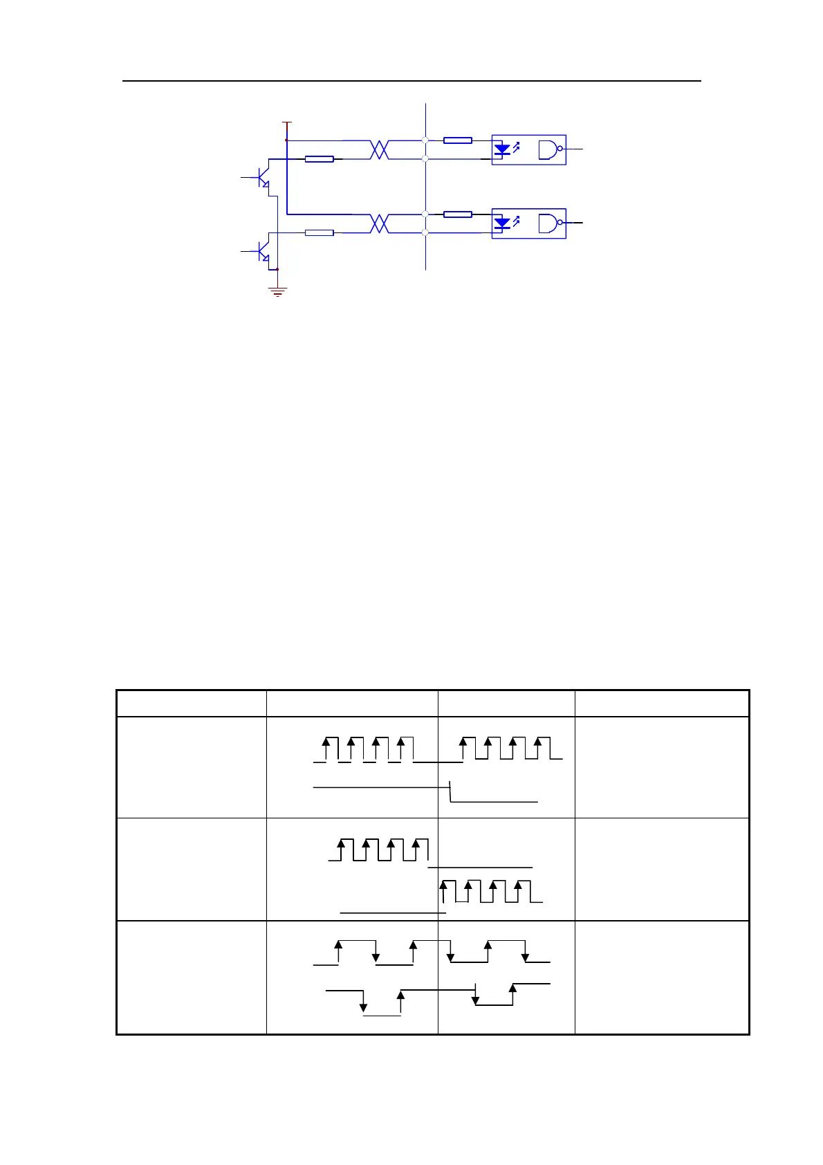
控制装置侧
PULS+
PULS-
SIGN+
SIGN-
R
R
VCC
Fig. 3.8 Single terminal drive mode of pulse volume input interface
(1) It is suggested to apply differential drive mode to correctly transmit pulse volume
data;
(2) AM26LS31, MC3487 or RS422 linear driver are employed in the differential drive
mode;
(3) Action frequency will be reduced in single terminal drive mode. According to pulse
volume input circuit, Resistance R is determined by the max. 25V voltage of external
power and 10 ~15mA drive current of the pulse input circuit. Practical data:
VCC=24V,R=1.3~2K;VCC=12V,R=510~820Ω;VCC=5V,R=82~120Ω.
(4) Refer to Table
3-4 about pulse input form, arrowhead indicates counting curb, and
Table
3-5 shows pulse input time sequence and parameter. If two-phase input
form is employed, 4-fold pulse frequency is less than 500kHz.
Table
3-4 Pulse input pattern
Pulse instruction form CCW CW Parameter setting value
Pulse string sign
PULS
SIGN
0
Instruction pulse +sign
CCW pulse string
CW pulse string
PULS
SIGN
1
CCW pulse /CCW pulse
A phase pulse string
B phase pulse string
PULS
SIGN
2
2-phase instruction
pulse
Controller side