Chapter 3 System configuration and assembly
25
3.5.2 Speed control
Single- or
three- phase
AC 220V
KM1
R
S
T
r
t
COM+
38
COM+ 39
SON 23
ALRS 8
FSTP 24
RSTP 9
SC1
40
SC2
FIL
25
RIL
34
10
DC 12~24V
Servo on
Alarm cancellation
CCW drive stop
CW drive stop
CCW torque limit
CW torque limit
SRDY
20
ALM 5
RLYOU+ 22
RLYOU- 21
Servo ready
Servo alarm
Speed in position
Output common terminal
reserved
reserved
U
V
W
PE
55V
6
5V
17
5V
18
5V
1
0V
20V
3
0V
4
0V
24 A+
12
A-
23
B+
11 B-
22 Z+
10
Z-
21
U+
9U-
20 V+
8
V-
19
W+
7W-
13 OH
16
0V
14 FG
15 FG
CN1
CN2
2
3
4
1
2
3
4
7
5
8
6
9
10
13
11
14
12
15
1
encoder
Motor
DA98B
AC servo
GIN1
35
11
Universal input 1
41
Universal output 1
HOLD+ 7
HOLD-
6
Hold release signal
Hold release signal earthing
CZ+
37
CZ- 36
Z-phase output of encoder
Z-phase output earthing of encoder
GOU1
SCMP
DG
DG
32
33
1k
27
12
28
13
42
43
PAOUT+
PAOUT-
PBOUT+
PBOUT-
PZOUT+
PZOUT-
A
B
Z
CN1
CN1
31
44
PE
PE
Pulse feedback A
Pulse feedback B
Pulse feedback C
Speed choice 1
Speed choice 2
1
17
AGND
VCMD
Speed instruction
(-10V +10VDC)
Speed instruction earthing
19
26
ZSP
ZSL
Zero-speed clamping input
Zero speed output of motor
DGND
2
Vcc
GND
A+
A-
B+
B-
Z+
Z-
U+
U-
V+
V-
W+
W-
FG
FIL
one-axis controller
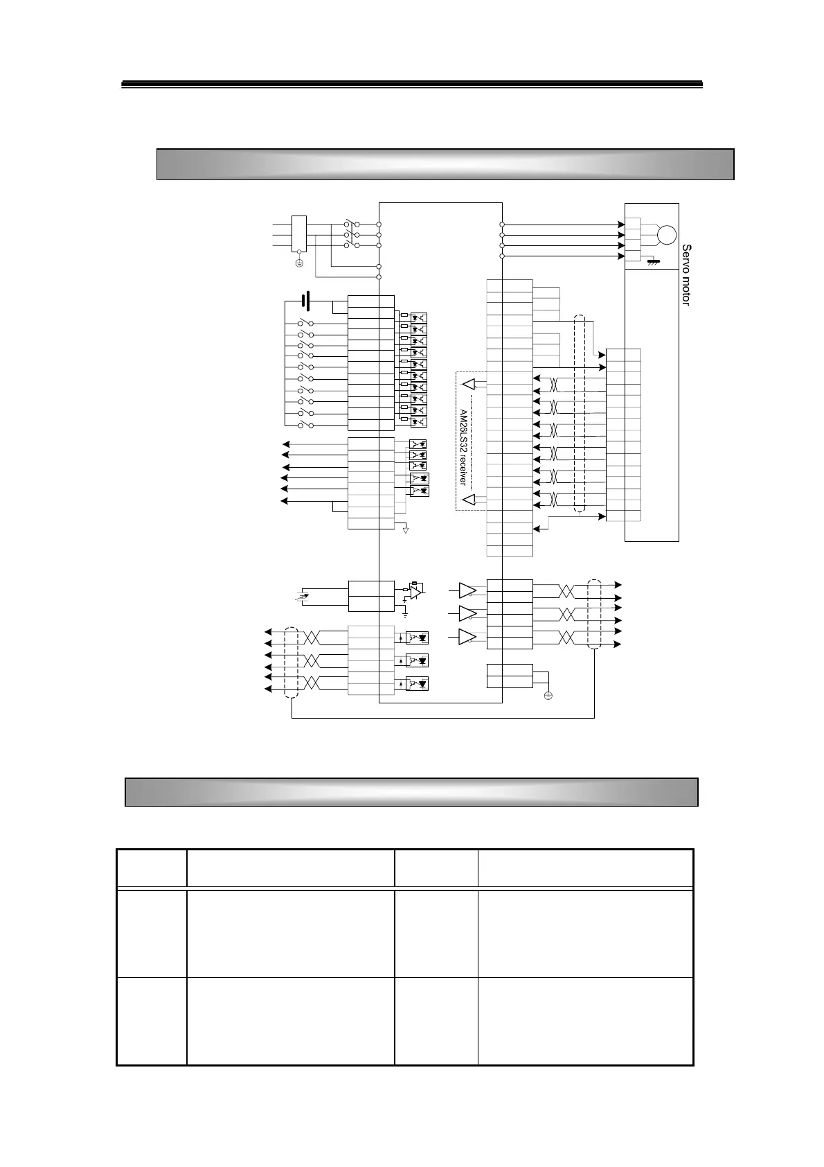
Fig3.14 Standard wiring for speed control mode
Table 3-7 Terminal functions for speed control mode
Sign Function Sign Function
SON
Servo on input terminal
PAOUT+
PAOUT-
Encoder A phase differential positive
output
Encoder A phase differential
negative output
ALRS
Alarming cancellation input
terminal
PBOUT+
PBOUT-
Encoder B phase differential positive
output
Encoder B phase differential
negative output
Standard Wiring
Terminal functions for speed control mode