GSK CNC Equipment Co., Ltd.
52
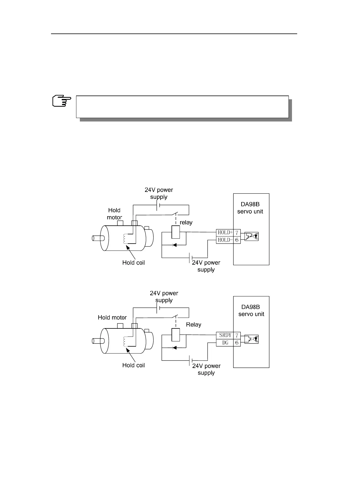
6.3 Application of hold release signal
In order to lock the vertical or tilted work table linked with the motor against falling down by
the servo power off, servo motor with hold brake is usually employed. The hold releasing
signal (HOLD±)is provided for the effective control of the motor with hold in the servo unit.
Fig.6.6 shows the wiring applied for the control of motor by the hold release signal. The 24V
power supply in the map is provided by user. The polarities of power should be noticed
when switching on the hold release signal(HOLD±). The time sequence of SRDY and
HOLD± are identical and they both can be used for the hold release signal for special
purpose. The wiring is as following.
Fig. 6.6 ( a ) Typical instance of the HOLD± hold release signal
Fig. 6.6 ( b ) Typical instance of the SRDY hold release signal
The Fig.6.7 shows the time sequence sketch map of normal hold release signal. When the
servo on(SON)is switched off, the motor’s actuation is cut off in suspense. Cut off the
motor’s actuation if the motor shaft is completely clamped after the power off of hold coil.
The latency is defined by parameter PA52.
The hold brake is only for work table hold and is not allowed to be
used for reduction and stop of machine.