Chapter 6 Trial run
51
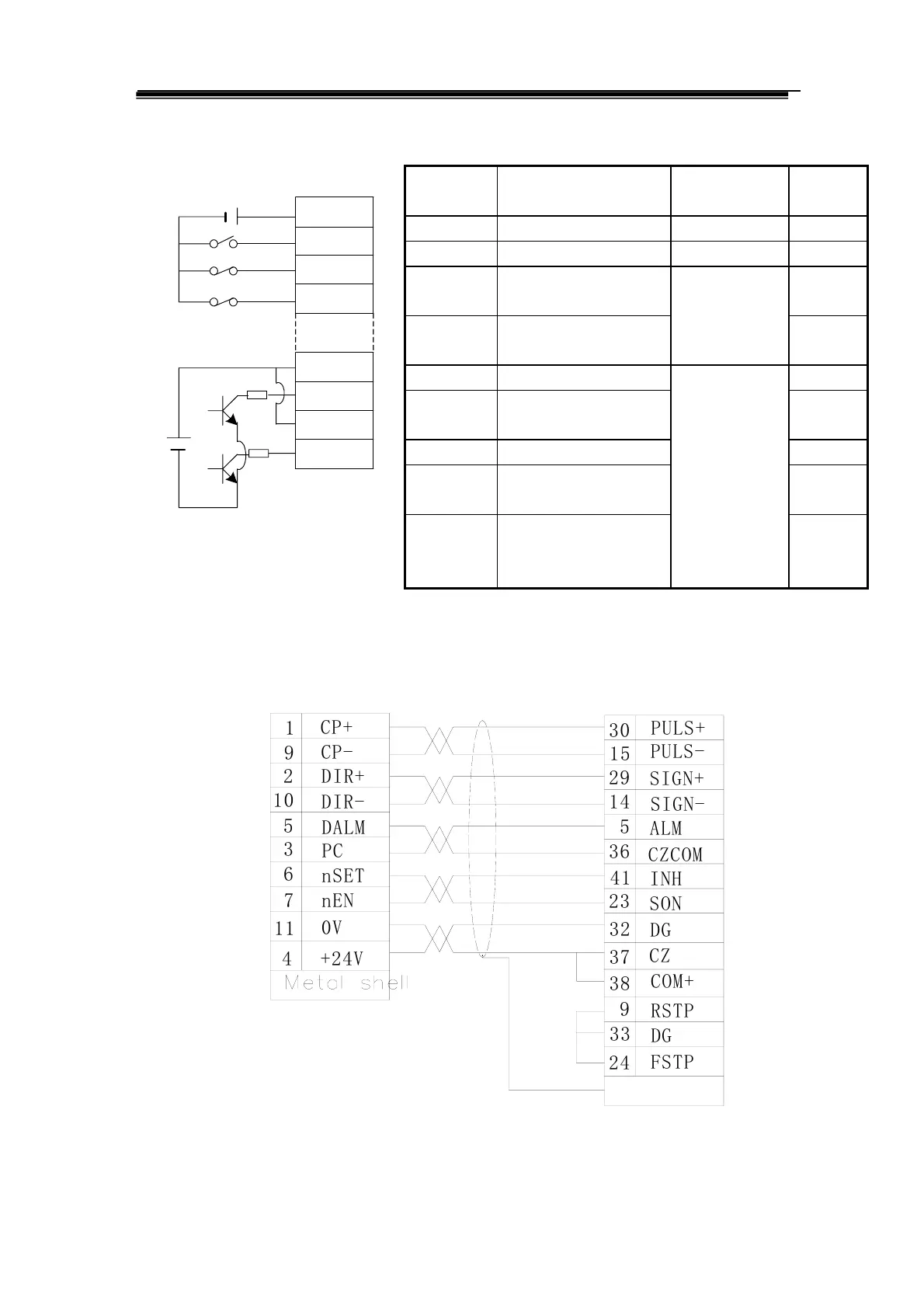
Wiring diagram block Parameter list
Sequence
number
Name Setting Factory
setting
PA04 Control mode selection 0 1
PA14 Pulse input mode 0 0
PA12 Orientation instruction
dividing numerator
1
PA13 Orientation instruction
dividing denominator
See Section
6.2.5.
1
PA05
Speed gain
PA06 Time constant for speed
integral
PA09 Orientation control gain 40
PA10 Orientation feedforward
gain
0
PA11 Cut-off frequency of
orientation feedforward
instruction filter
Adjust it by
requirement.
See parameter
adjustment in
Section 6.4.
300
Fig.6.4 Wring of orientation instruction control
Wiring sketch map for CNC system of GSK980TD turning machine
S
O
N
P
U
L
S
+
P
U
L
S
-
S
I
G
N
+
S
I
G
N
-
C
Z
C
O
M
C
O
M
+
R
S
T
P
F
S
T
P
n
E
N
n
S
E
T
C
P
+
C
P
-
D
I
R
+
D
I
R
-
D
A
L
M
+
2
4
V
7
1
1
4
0
V
1
1
0
6
5
3
P
C
2
9
2
3
2
4
3
8
9
3
3
D
G
3
2
3
7
D
G
C
Z
3
0
1
4
5
3
6
4
1
A
L
M
I
N
H
2
9
1
5
Metal shell
DB44(female plug)
DB15(male plug)
GSK980TD(X or Z axis)
XS30 or XS31
DA98B CN1
Fig.6.5 Valid pulse instruction
COM+
SON
FSTP
RSTP
DC
12-24V
38
23
24
9
PLUS+
PLUS-
SIGN+
SIGN-
70
70
DC
5V