Chapter 6 Trial run
47
with zero speed. If the motor runs in low speed, adjust the parameter PA22 to make the
motor to be in zero speed state.
3) Slowly adjust the analog voltage, the motor speed will vary by the voltage variation. The
highest motor speed in ±10V input voltage can be adjusted by modifying parameter
PA29. Be attentive that the highest running speed is limited by PA23.
4) Modify parameter PA19 if the rotation direction is required to be changed.
When PA19=0, motor runs forward (CCW) for positive voltage, backward(CW) for
negative voltage;
When PA19=1, motor runs backward (CW) for positive voltage, forward(CCW) for
negative voltage;
5) If vibration occurs in the CNC closed loop running, adjust parameter PA08 for feedback
filtering.
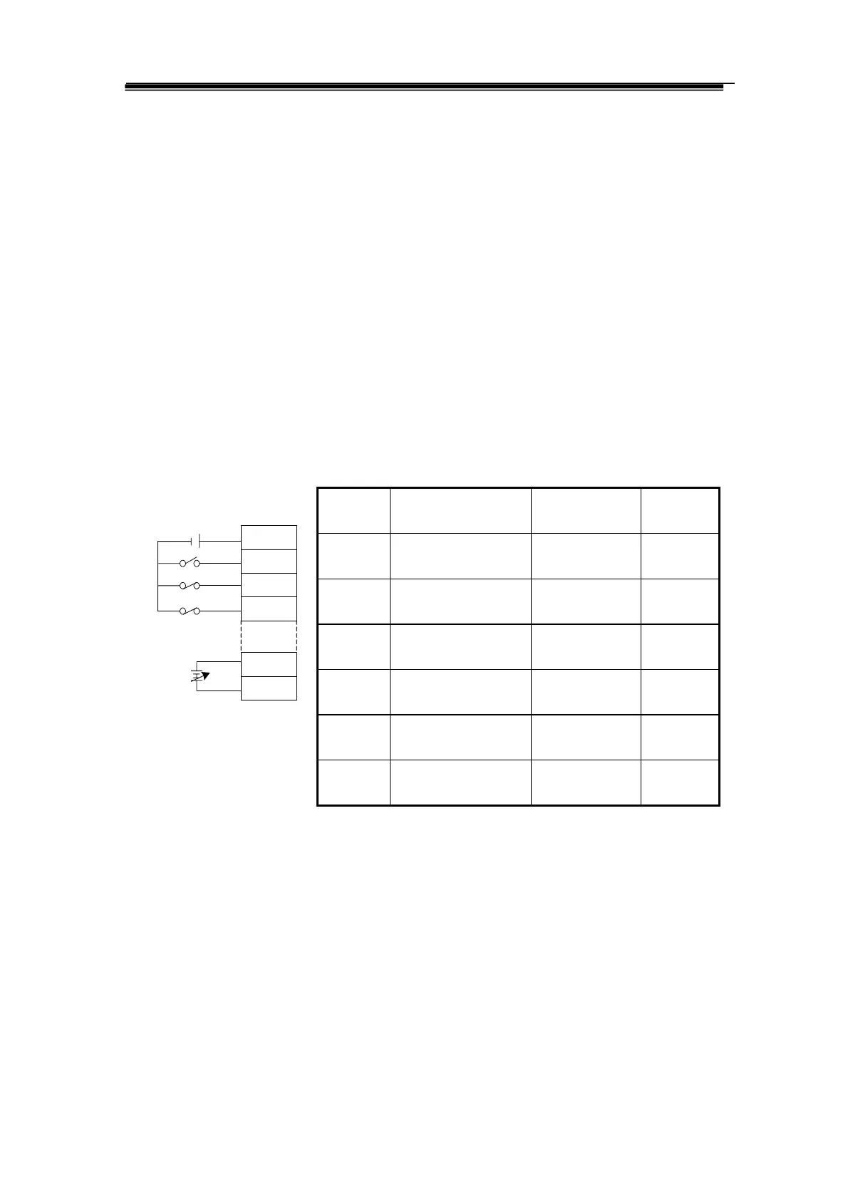
Wiring diagram block: pameter list
Sequence
number
Name Setting range Factory
setting
PA04 Control mode
selection
0~6
1
PA08 Low pass filter for
speed detecting
1~5000
200
PA19 Reverse of analog
speed
0~1
0
PA22 Instruction deviation
of analog speed
-500~500
0
PA23 Highest speed setting
for motor
-30000~30000
25000
PA29 Highest speed of
analog instruction
-30000~30000
25000
Fig.6.2 Wiring for analog instruction control
Wirings for two types of CNC system for milling machines made by us.
COM+
SON
FSTP
RSTP
VCMD
AGND
DC
12-24V
DC
-10V-+10
38
23
24
9
17
1