Chapter 4 Parameter
29
7: Motor torque display;
8: Motor current display;
9: Linear speed display;
10:Control mode display;
11: Orientation instruction pulse frequency display;
12: Speed instruction display;
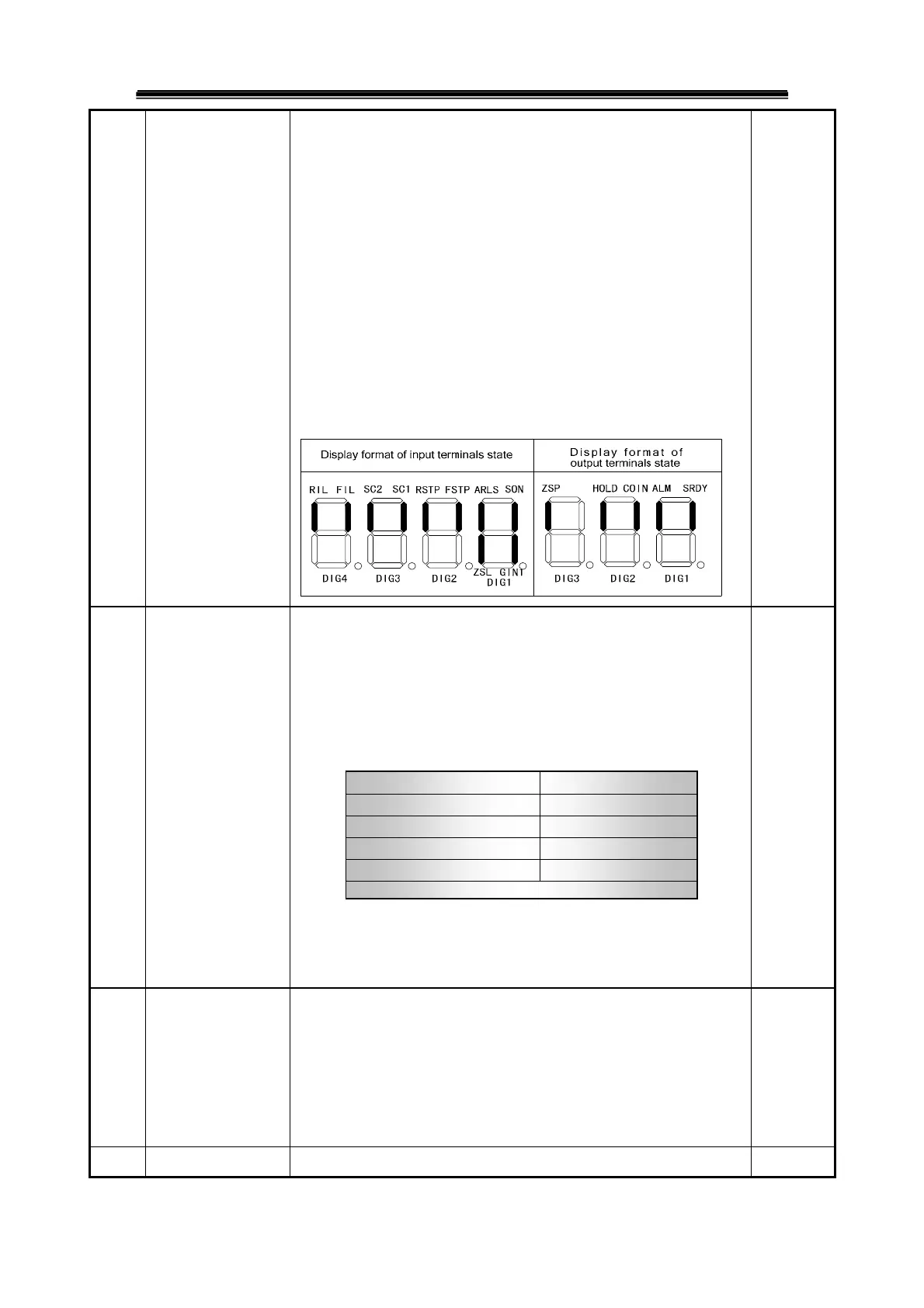
15: Input terminal state display;
16: Output terminal state display;
17: Encoder input signal display;
18: Running state display;
19: Alarm code display;
20: Reserved.
PA 04 Control mode
selection
Set control mode of the servo unit by the parameter:
0:Orientation control mode, orientation instruction input by pulse input
port
1:Speed control mode, speed instruction input by VCMDIN, VCMDINC
analog input terminals
2:Internal speed control mode
3:Manual mode
4:JOG mode
5:Encoder zero-adjusting mode
0~5
PA 05 Speed proportional
gain
① Proportional gain set of speed loop regulator
② The bigger the setting value is, the higher the gain is and the bigger
the rigidity is. Parameter value is
determined by specific servo unit
model and load. Generally, the bigger the load inertia, the bigger the
setting value is.
③ Set the bigger value if there is no vibration for system.
5~2000Hz
PA 06 Speed integral time
① Integral gain set of speed loop regulator
1~1000ms
SC2 SC1
Internal speed
OFF OFF 1
OFF ON 2
ON OFF 3
ON ON 4