COMMUNICATION INTERFACE
171
232 or PSU-485 connection kit.
3. Plug in intermediate connector to the OUT port
on the first unit then using the slave serial link
cable (black plug) to connect intermediate
connector to the IN port of the second unit.
4. Connect all the remaining units in the same
fashion until all the units have been daisy-
chained together.
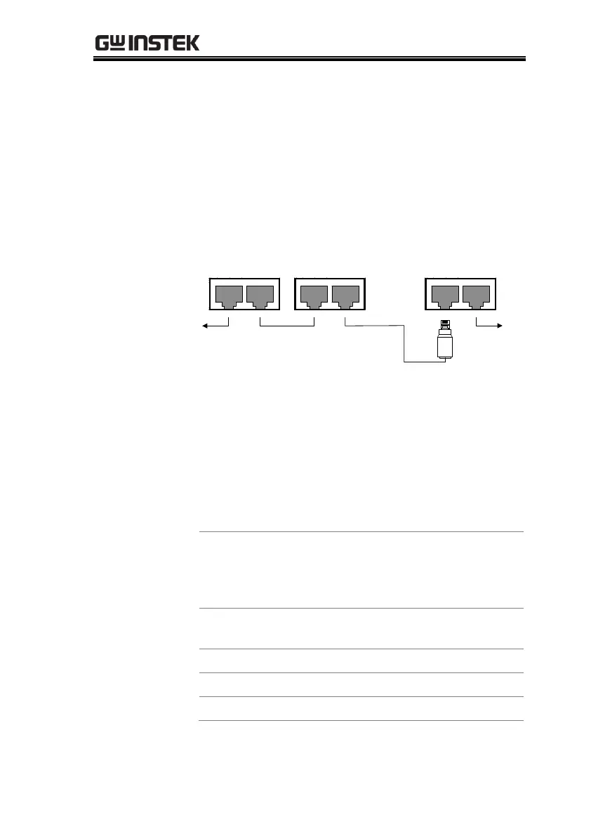
RS 485 / 232
OUT IN
Unit #1
RS 485 / 232
OUT IN
Unit #2
RS 485 / 232
OUT IN
Unit #N
End terminal
connector
To PC
RS232/RS485
serial cable
Slave serial
cable(black plug)
Slave serial
cable(black plug)
Intermediate
connector
5. Terminate the OUT port of the last unit with the
end terminal connector included in the PSU-
232 or PSU-485 connection kit.
6. Press the Function key to enter the
Normal configuration settings for
the master unit.
Set the following settings:
Configure the master unit as you
normally would for RS232 or
RS485 remote control, see page
165.
Set the baud rate (set all units the
same). See page 165.
 Loading...


