4-61
RPS status LED
The S5130S-28P-HPWR-EI, S5130S-52P-PWR-EI, S5130S-10MS-UPWR-EI,
S5130S-28S-HPWR-EI, S5130S-52S-PWR-EI, and S5130S-28MP-HPWR-EI switches support
RPS input and each provide an RPS status LED on the front panel to indicate the RPS operating
status.
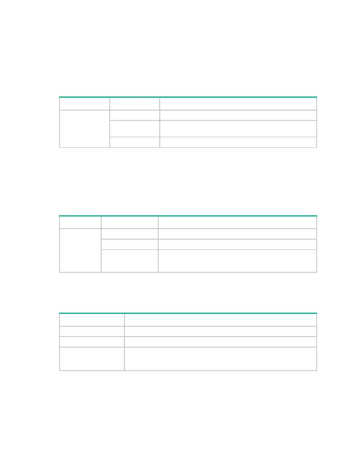
Table4-16 RPS status LED description
LED mark Status Description
RPS
Steady green Both the RPS DC input and the AC input are normal.
Steady yellow
The RPS DC input is normal, but the AC input is disconnected or
has failed.
Off The RPS DC input has failed, or no RPS is connected.
Mode LED (MODE)
Each PoE switch provides a mode LED (MODE). The mode LED works in conjunction with the
Ethernet port LEDs to indicate the operating state of the Ethernet ports and the switch.
You can use the LED mode switching button to change the indication of the mode LED.
Table4-17 Description for the mode LED
LED mark Status Description
Mode LED
(MODE)
Steady green The Ethernet port LEDs are showing link state of the ports.
Flashing green The Ethernet port LEDs are showing the PoE status of the ports.
Flashing yellow
The Ethernet port LEDs work in conjunction to indicate the IRF
member ID of the switch. For example, if the LED for port 5 is
steady green, the IRF member ID of the switch is 5.
SFP/SFP+ port LED
Table4-18 SFP/SFP+ port LED description
Status Description
Steady green A link is present on the port.
Flashing green The port is sending or receiving data.
Off
• No link is present on the port.
• The mode LED is operating in PoE mode (available only for PoE switch
models)
Ethernet port LEDs
On a PoE switch, the following Ethernet port LEDs work in conjunction with the mode LED to indicate
the operating state of the Ethernet ports and the switch from different aspects. Table4-19 describes
the Ethernet port LEDs on a PoE switch.
10/100/1000BASE-T autosensing Ethernet port LEDs

 Loading...


