20
90
80
85
BL
BM
BO
!
"
$
#
/
%
&
)
*
BN
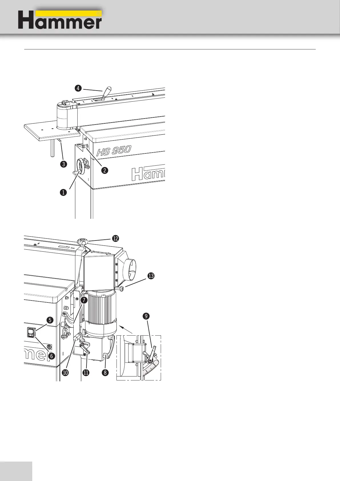
Edge sanders
HS 950
!
Handwheel - Height adjustment
Height adjustment (Work bench)
"
Clamping lever
Clamp - Height adjustment (Work bench)
#
Clamping lever
Clamp - Height adjustment (side working table)
$
Chuck lever - Changing the sanding belt
Tool free handling when changing the sanding belt
%
Green push button
Switching on the machine
&
Red push button
Emergency stop and switching off the machine
/
Scale - Sanding module inclination
Angle display 0°-90°
(
Hand grip
Sanding module inclination
)
Clamping lever - Sanding module inclination
angle adjustment clamp
BL
Adjustment handle - Oscillating sanding
Adjustment - Oscillating range
BM
Clamping lever - Oscillating sanding
Oscillating range adjustment clamp
BN
Clamping lever - Infeed fence
End stop clamping
BO
Clamping lever - extraction flap
Extending the machining area (long workpieces)
5.4 Operation and display elements
Setting up the machine
Fig. 5-5: Operation and display elements
Fig. 5-6: Operation and display elements