28
/
(
)
BL
"
!
"
!
#
Edge sanders
HS 950
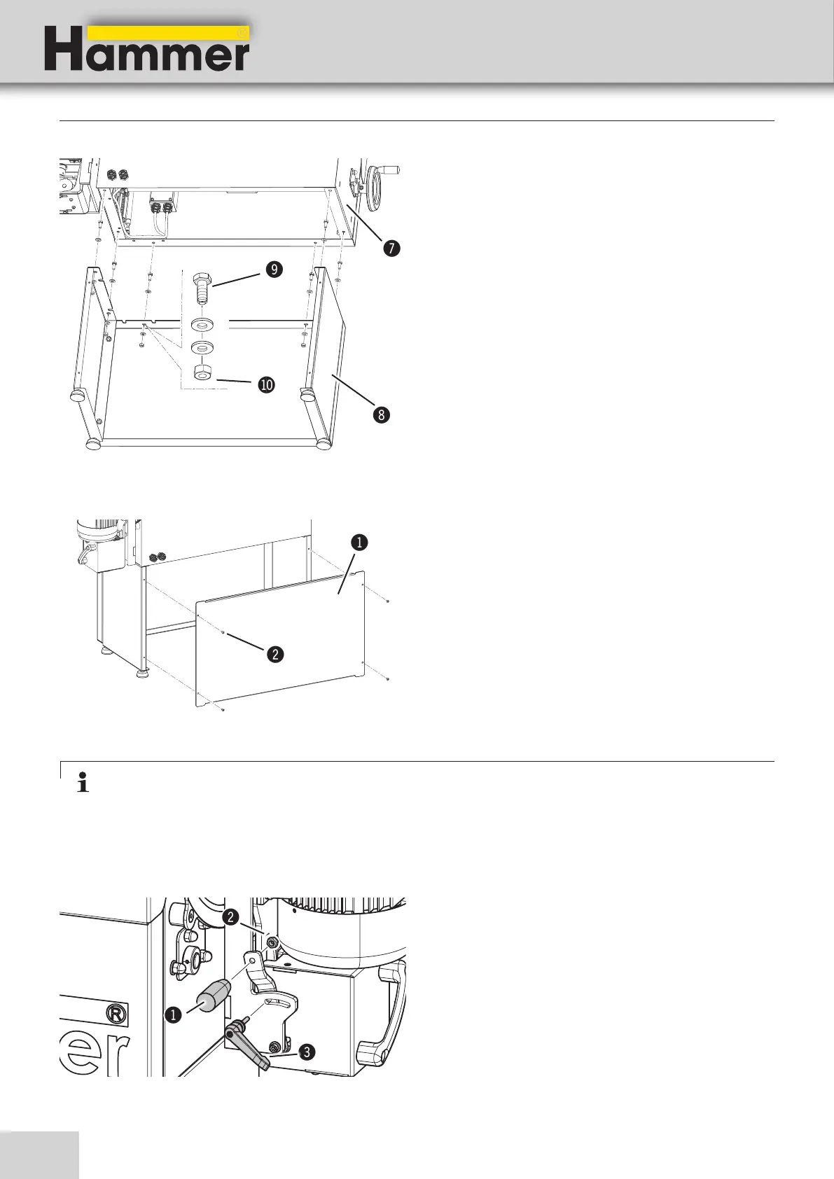
3. Place the machine stand on the machine frame.
Take measures to prevent the machine from slipping
sideways.
4. Thread the screws (6 x M8) through the holes of both
stands and fasten with nuts.
/ Machine base-frame
( Machine frame
) Screw (M8)
BL Mutter (M8)
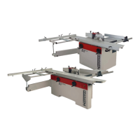
1. Thread the adjustment handle into the hole of the
adjustment lever.
2. Lock the nut with a spanner. (M8)
3. Mount clamping lever /screw in
! Adjustment handle
" Nut (M8)
# Clamping lever
5. Tighten the cover plate with the hex screws (4 x M6).
! Cover plate
" IAllen key (M6)
Setup and installation
Fig. 7-5: Assemble machine frame
Fig. 7-6: Assemble machine frame
Fig. 7-7: Assembly - Adjustment handle
7.3.2 Assembly - Adjustment handle / Oscillating range adjustment clamp
Note:
If the machine stand is not mounted on the machine frame, the machine must be placed on a stable and level
surface at least 490 mm high.