27
L
B
H
!
"
$
#
%
&
!
"
Edge sanders
HS 950
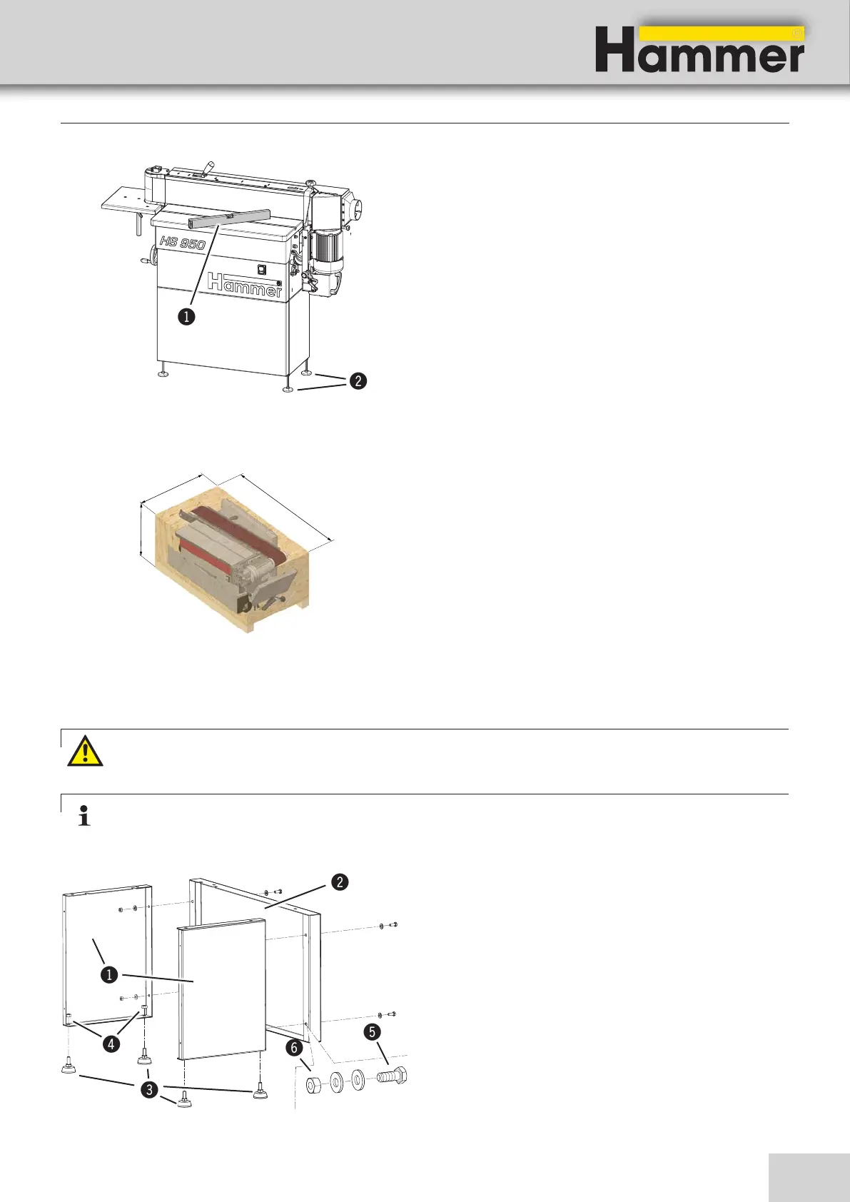
The machine is shipped mounted on a pallet.
Carefully remove the lid and side walls of the pallet.
Store the loose components cleanly and safely.
Remove the transport brackets before moving the machi-
ne to the installation location
1. Fix the adjusting screws with the nut (4 x M10) to the
side sheet metal parts.
2. Fasten the two side sheet metal parts onto the sheet
metal front part using the screws and nuts (4 x M8).
! Side sheet metal
" sheet metal front
# Adjusting screws
$ Nut (M10)
% Screw (M8)
& Nut (M8)
1. Transport the machine to the installation site as
instructed in the “Transport“ chapter and the enclo-
sed transport or installation instructions.
2. Position the machine with the aid of a spirit level
to ensure that the machine functions precisely and
operates smoothly.
Even out uneven floors by setting the adjusting screw
or by bolstering the machine.
! Spirit levels
" Adjusting screws
Setup and installation
7.3 Machine assembly
Fig. 7-2: Positioning the machine
Fig. 7-3: Machine packaging
7.3.1 Assemble machine frame
Warning! Heavy dead weights can easily cause an injury
To facilitate assembly, ensure the presence of a minimum of one additional people.
Take measures to prevent the machine from slipping sideways.
Note:
During the assembly of the machine frame, first loosely connect all parts.
Finally, tighten all screws.
Fig. 7-4: Assemble machine frame