ASSEMBLY AND INSTALLATION
25
6
3
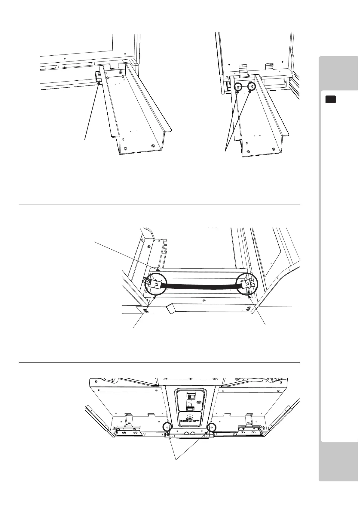
Remove the xings securing the GUN CABINET.
FIG. 6-6d
2
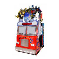
After securing the JOINT BRIDGE units, on the left hand side (JOINT BRIDGE L), feed the wiring
harnesses through the JOINT BRIDGE L and connect to the REAR CABINET harnessing.
MONITOR CAB HARNESSING
REAR CAB HARNESSING
JOINT BRIDGE L
M8 FIXINGS
(FROM SEAT)
FIG. 6-4e
Fixings to Monitor Cab
Fixings to Rear Cab
FIG. 6-4c
PLATE JOINT BRIDGE SECURE
HIGH STRENGTH STUD
 Loading...