ASSEMBLY AND INSTALLATION
23
6
3
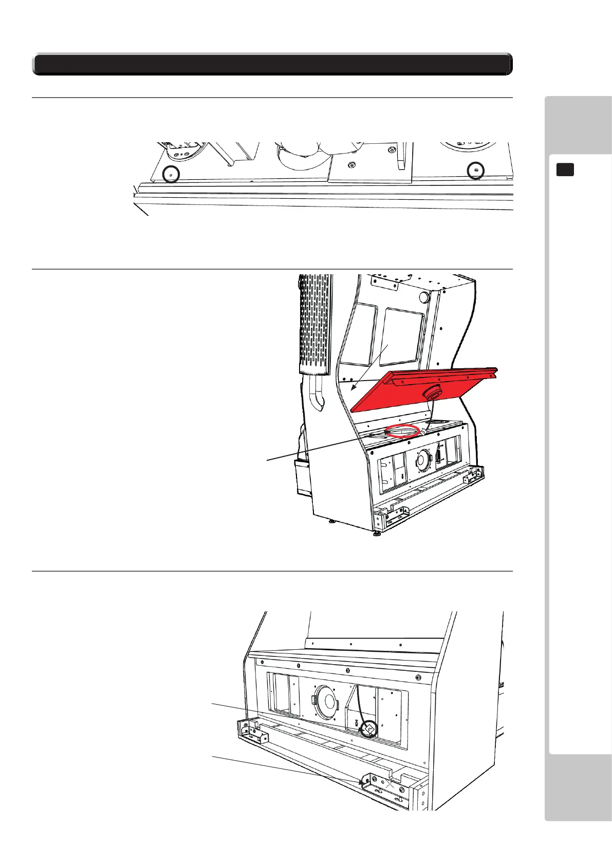
Position the harness wiring located underneath the seat towards the JOINT BRIDGE SECURE R. This will
need to be connected to the harnessing from the MONITOR CABINET via the JOINT BRIDGE L when the
two cab sections are joined together.
2
Starting at an angle, place the seat panel into
position, taking care not to trap or damage the
harnessing wires. Feed the harnessing wire
through the hole in the centre of the seat.
6-3 ATTACHING THE SEAT
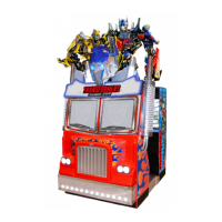
1
Remove the seat panel by unfastening the (2) M8 xings securing the transit brackets holding it in place.
FIG. 6-3a
FIG. 6-3b
FIG. 6-3c
HARNESSING CONNECTOR
FEED HARNESSING THROUGH
JOINT BRIDGE SECURE R
 Loading...