9
15
1
8
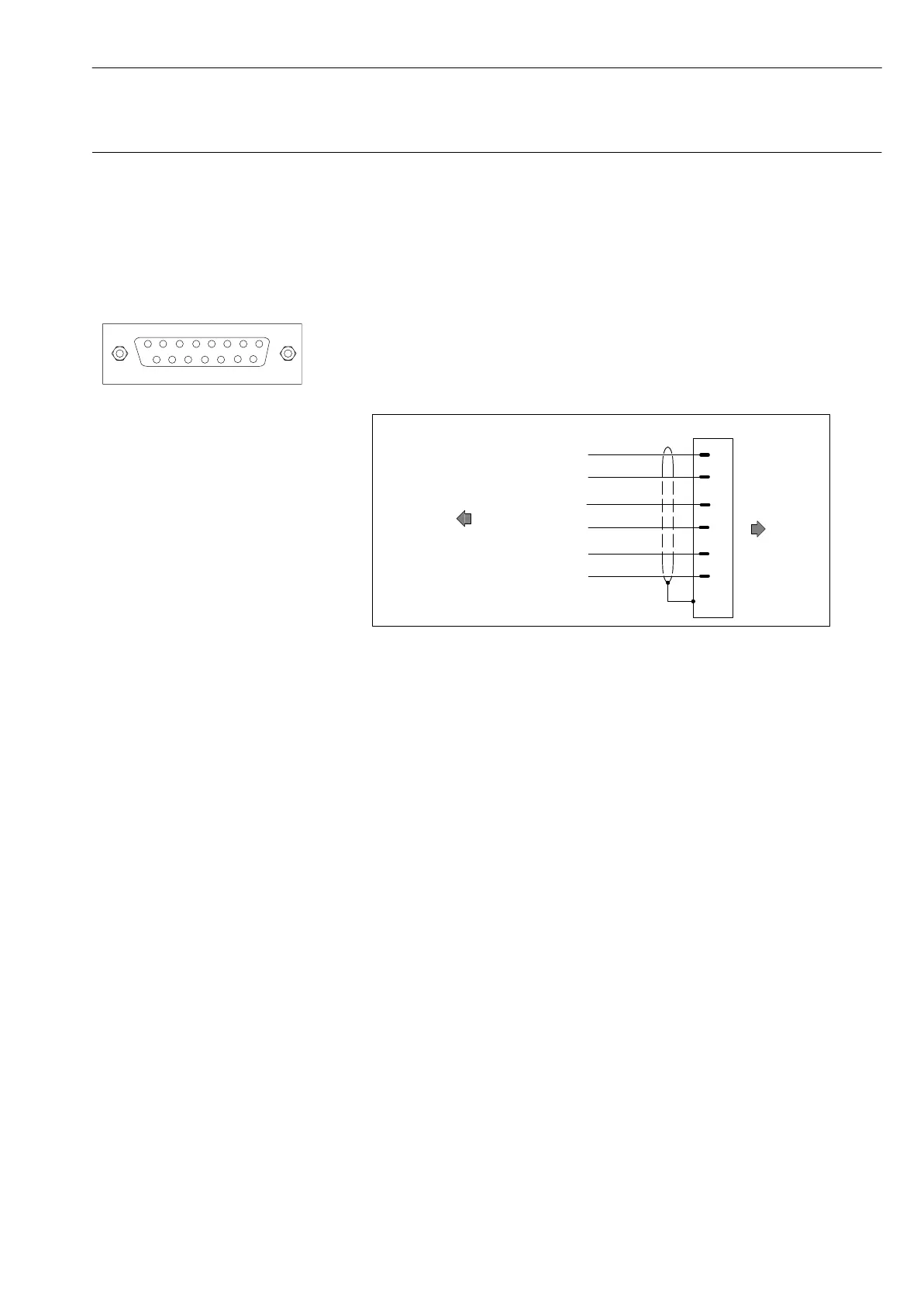
15-pin socket for
transducer connection
Spider8: Channels 0-3
(optionally 4-7)
D-7
Connecting Ý Connecting transducers
Spider8
Use the transducer cable directly for connecting or use additional
KAB133A adapter cable.
Connecting to a carrier-frequency module (15-pin socket, sub-D
connector Bu):
D The transducer cable is unterminated:
Fit a 15-pin connector (see Fig. D 1)
(Ord. No. 3-3312 0182)
wh
rd
bk
bu
gn
gy
5
6
8
13
12
15
sub-D
connector
15-pin
unterminated
Spider8
Transducer
Bridge excitation voltage
Bridge excitation voltage
Measurement
signal
Sensor circuit
Sensor circuit
Measurement
signal
Fig. D 1: Unterminated transducer connection cable