Electrical connection
T10FS A0785-150 HBM: public 49
the tolerances of the excitation voltage supply
To allow for adaptation to the various conditions, there
are three switches in the stator housing, which can be
accessed by removing the stator cover (see Fig. 6.3).
Switch
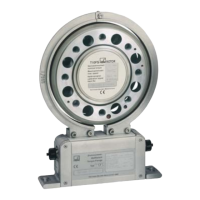
Fig. 6.3 Switches in the stator housing
Switch
position
Example applications
1
a) Older amplifiers
b) For when the calibration signal is unintentionally initiated
with very short cables
2 Normal position (factory setting)
3 For cable lengths in excess of approx. 20 m
Please ensure that after changing to switch position 3,
the calibration signal is not initiated.

 Loading...