HT# 059299-00 A
• Select a location near the equipment to be
controlled
• The surface should be at, sufciently wide, and
strong enough to hold the Multi-MOD
• Installation location should be away from extreme
heat, cold, or humidity
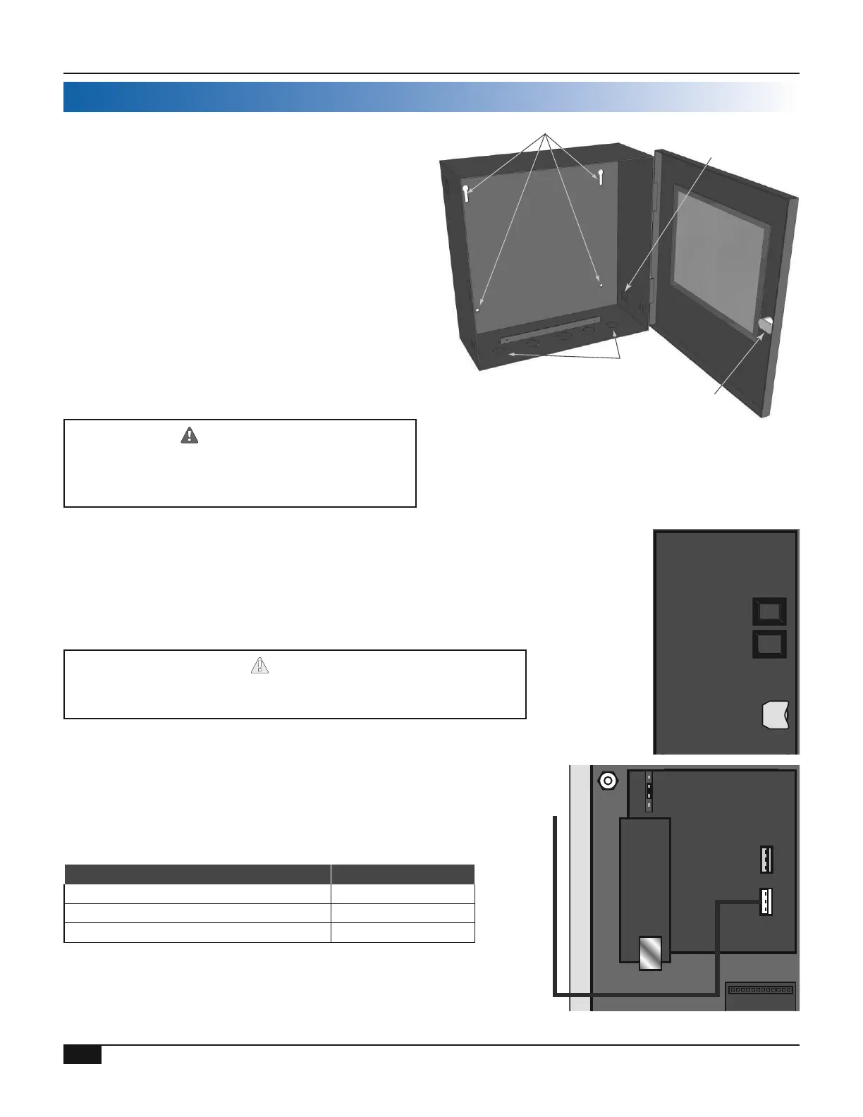
• Remove the control from its enclosure by removing
the top center screw and loosening the two bottom
screws
• Screw the enclosure to the surface through the
mounting holes in the back of the enclosure
• Return the panel to the enclosure Replace the top
screw and tighten the bottom two screws
Use existing the Enclosure Knockouts
DRILLING HOLES THROUGH THE CONTROL
ENCLOSURE VOIDS CONTROL WARRANTY
Mounting Holes
Communication
Knockout
Wiring
Knockouts
Enclosure
Lock
• Turn the Multi-MOD Platinum panel over to reveal the
piggyback circuit board (CPU board)
• Remove the plastic strap the covers the battery The contacts
should be touching the battery
Do not install the battery unless you plan to power the control at once
If the control is not powered, the battery will lose its charge in 100 days
CPU Board
Battery
Ethernet
RS485
Main Board
Control Stages
A & B
Control Stages
C & D
A1
G1
B1
A2
G2
B2
RS485
Communication Board
(HT# 900234-20-XXX)
• If a control is ordered as a standard control, it can be eld
upgraded to have communication by adding the appropriate
upgrade kit A new CPU board and a communication board will
be included in any of the Upgrade Kits
Multi-MOD Internet Upgrade Kit 900204-20-RINet
Multi-MOD BACnet IP or MSTP Upgrade Kit 900204-20-BAC
Multi-MOD Modbus Upgrade Kit 900204-20-BUS
• All Communication to Modbus RTU or BACnet MSTP must use
the RS485 on the control's Communication Board
N
5V
8V
Ethernet
RS485
Main Board
Control Stages
A & B
Control Stages
C & D
A1
G1
B1
A2
G2
B2
RS485
Communication Board
(HT# 900234-20-XXX)
Connect to BACnet MSTP Network
or MODBUS RTU Network
RS485 Cable