HT# 059299-00 A
• The RS485 cable length must not exceed 3500 feet
• The RS485 cable must use one of the Platinum control’s
enclosure side knockouts Do not use bottom knockouts for
communication cabling
• Connect the RS485 cable coming from the BACnet MSTP or
Modbus network to the Black RS485 communication socket on
the back of the control’s Communication Board The terminals
are labeled ‘A1 (+)’, G1 (Ground), and ‘B1 (-)’
The RS485 Ground terminal (G) MUST be
connected to the BMS RS485 Ground
• The Ethernet cable must use one of the Platinum control’s
enclosure side knockouts Do not use bottom knockouts for
communication cabling
• For reliable communication, the maximum Ethernet cable run
must not exceed 200'
• Use only CAT-5E Ethernet cable or better when connecting
from the Internet Modem, router or the IP network to the
Ethernet RJ45 communication socket on the back of the
control’s Communication Board
Class 1 voltage wiring (low voltage) must use a different knockout
and conduit from any Class 2 voltage wiring (high voltage)
N
5V
8V
Ethernet
RS485
Main Board
Control Stages
A & B
Control Stages
C & D
A1
G1
B1
A2
G2
B2
RS485
Communication Board
(HT# 900234-20-XXX)
Connect to BACnet IP Network
or the Internet
CAT5-E Cable
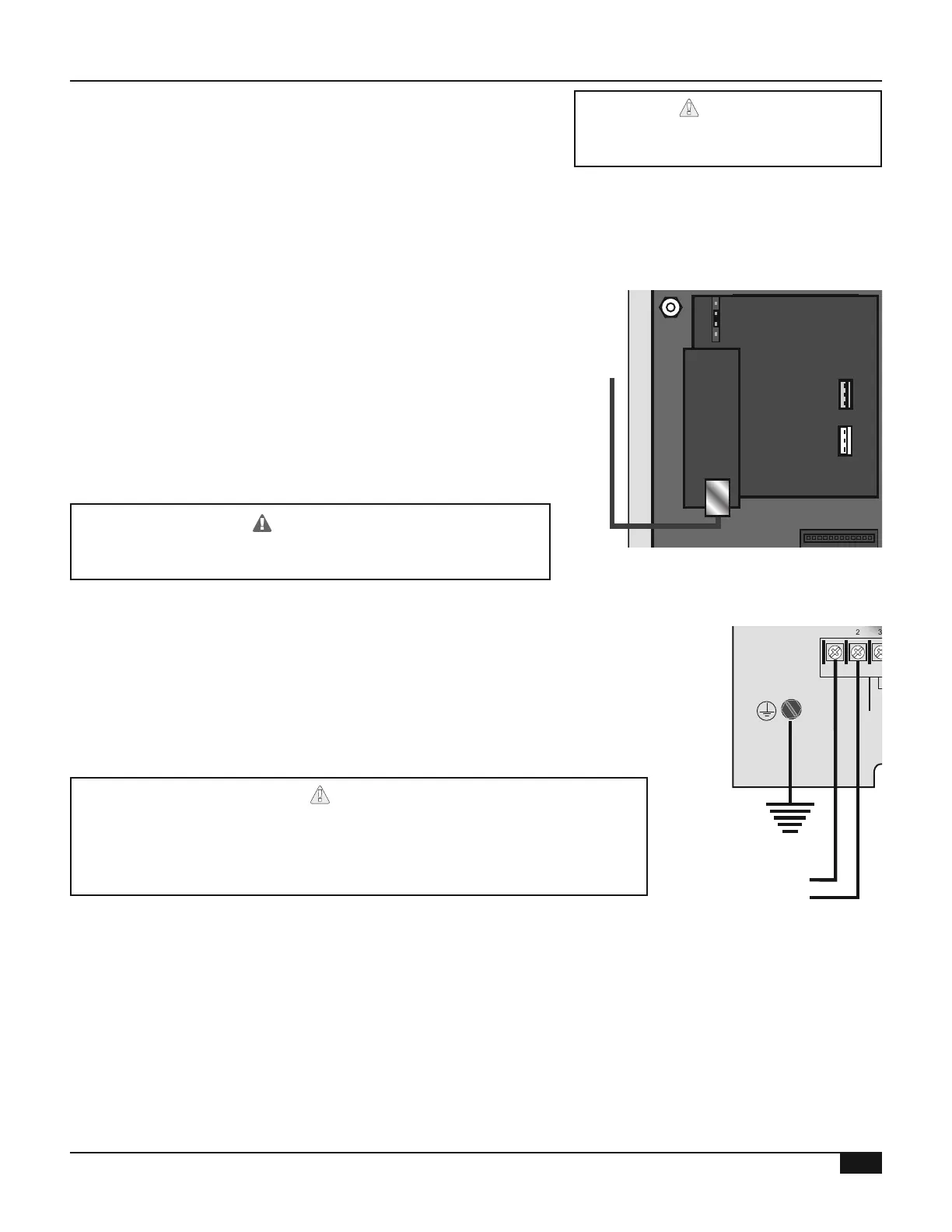
• Bring the 120VAC power wires through the enclosure's bottom knockouts
• Connect the hot line to the Line terminal (1) and connect the neutral line to
the Neutral terminal (2) Connect the green screw to Earth Ground
• Heat-Timer recommends the installation of a surge suppressor and a
power switch before the power line connection
• Use a separate circuit breaker for the control Do not share the control power
with other major equipment, pumps and motors
• Output relays do not source any power A separate power source must be
used Use the output relay to enable or disable the equipment
• Output relays do not source any power If the equipment connected to an
output relay requires power, an external power source must be used
• To use an output, you must install a relay Relays must be ordered
separately (HT# 500054-00)
• Each output relay on the Multi-MOD is rated for 1 Amp (1/8 HP) at 120
VAC 60 Hz If higher relay rating is required, connect the equipment to an
external relay Use the Multi-MOD output relay to control the external relay
MADE IN U.S.A.
SAFETY
GROUND
MUST BE
CONNECTED
OUT
TEMP
PROVE
/DHW
STAGE
A
STAGE
B
MENU FUNCTIONS
SELECT enters menus or accepts changes
ADJUST selects menu items or changes settings
BACK returns to previous menu
PREV./NEXT steps through stage status
DEL deletes schedule settings
STAGE
(DAY)
HELP NEXT
PRESS TO
SELECT
BACK
ADJUST
A1
A2
A3
A4
A5
A6
A7
A8
A9
A10
A11
A12
STAGE
C
DO NOT APPLY ANY VOLTAGE
TO SENSOR TERMINALS
B1
B2
B3
B4
B5
B6
NETWORK
PRESS
4-20 mA
SHUTDOWN
SYSTEM
TEMP
INPUTS
ROUTE SENSOR AND AUXILIARY WIRES
THROUGH THIS KNOCKOUT ONLY
<A> B C D
100% 50% --- ---
T
T
OUTPUT RATINGS:
120VAC, 6A RESISTIVE
1A PILOT DUTY
15A TOTAL
FOR ALL CIRCUITS
INPUT RATINGS:
115VAC 60Hz
30VA MAX
USE COPPER WIRE,
CLASS 1 WIRE ONLY
ENCLOSED
ENERGY
MANAGEMENT
EQUIPMENT
LISTED
99RA
STAGE selects stage menus or next stage
DAY selects next day
SYSTEM B C DA
LINE
NEUTRAL
1 2
3 4
5 6 7 8 9 10 11 12
FULL MODULATION
SEQUENCING CONTROL
LOCKOUT
INPUTS
STAGE
D
B7
B8
OPERATING LIMIT
OUTPUTS
SIGNAL
SHIELD
+
EMS
MODULATION OUTPUTS
A B C
D
C1 C2 C3 C4 C5 C6 C7 C8 C9 C10 C11 C12
S
+
L
N
Earth
Ground
120VAC