HT# 059299-00 A
• An outdoor sensor must be used when selecting Reset °F or
Reset °C The sensor is used to calculate the system target In
addition it is used in the outdoor Cutoff See "Sensor Type" on
page 26 and "Outdoor Cutoff Temperature" on page 32
• If an outdoor sensor is installed in any of the set point options,
it will only be used in the outdoor Cutoff This feature will
automatically be activated when an outdoor sensor is connected
• Use only the Outdoor Sensor included with the unit
(HT# 904220-00)
• Locate the sensor on the north side of the building at least 10'
above the ground The sensor MUST never be in direct sunlight
• Be sure the location is away from doors, windows, exhaust fans,
vents, or other possible heat or cool sources
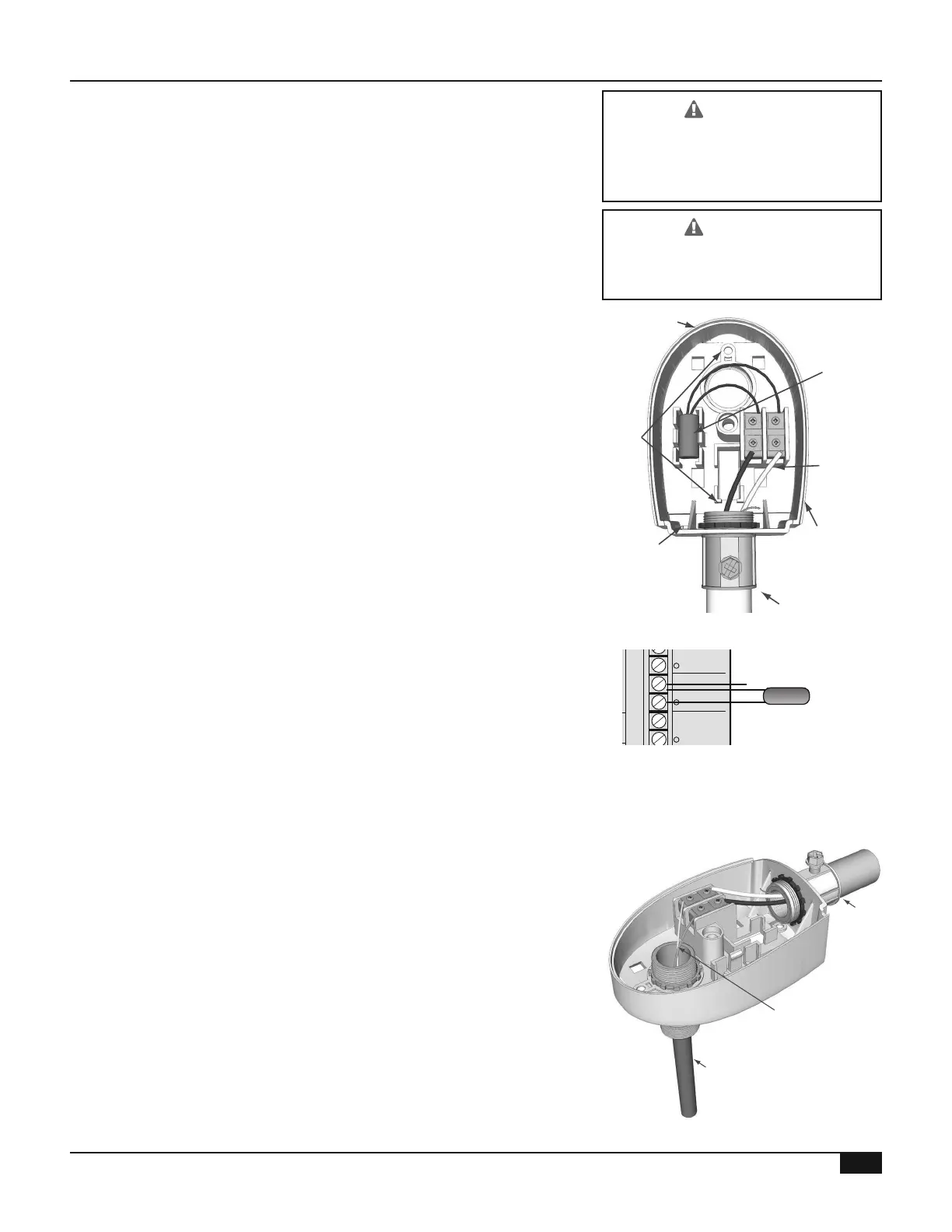
• Adhere the Outdoor Label to the back of the sensor base
• Use the Enclosure Base bottom knockout for the conduit Use
the locknut to hold the conduit and enclosure base together
Install and screw the cover to the base
• If screws are used to afx the enclosure to the wall, make sure to
seal around the sensor and wall except from the bottom
Class 1 voltage wiring (low voltage)
must use a different knockout and
conduit from any Class 2 voltage
wiring (high voltage)
To avoid damage to the Multi-MOD,
NO VOLTAGE can be applied to the
Multi-MOD Platinum input terminals
Outdoor Sensor
snap-in location
Shield
not connected
Conduit
Outdoor Label
on back of Sensor
Mounting
screws
location
Seal around
sensor and wall
Outdoor
drip-hole
• Connect the sensor wires to the Out Temp terminals
Temperature sensors have no polarity
• Connect the shield to terminal A12 with one of the other sensor
wires Do not connect the shield at the sensor end
• The sensor wires can be extended up to 500’ using 18 AWG
2-conductor shielded cable (HT# 703001-01)
MULTI-MOD
Platinum
MADE IN U.S.A.
PREV.
(DEL)
SAFETY
GROUND
MUST BE
CONNECTED
OUT
TEMP
/DHW
STAGE
A
STAGE
B
MENU FUNCTIONS
SELECT enters menus or accepts changes
ADJUST selects menu items or changes settings
BACK returns to previous menu
PREV./NEXT steps through stage status
DEL deletes schedule settings
STAGE
(DAY)
HELP NEXT
PRESS TO
SELECT
BACK
ADJUST
A1
A2
A3
A4
A5
A6
A7
A8
A9
A10
A11
A12
STAGE
C
DO NOT APPLY ANY VOLTAGE
TO SENSOR TERMINALS
B1
B2
B3
B4
B5
B6
NETWORK
PRESS
4-20 mA
SHUTDOWN
SYSTEM
TEMP
INPUTS
ROUTE SENSOR AND AUXILIARY WIRES
THROUGH THIS KNOCKOUT ONLY
<A> B C D
100% 50% --- ---
T
T
OUTPUT RATINGS:
120VAC, 6A RESISTIVE
1A PILOT DUTY
15A TOTAL
FOR ALL CIRCUITS
INPUT RATINGS:
115VAC 60Hz
30VA MAX
USE COPPER WIRE,
CLASS 1 WIRE ONLY
ENCLOSED
ENERGY
MANAGEMENT
EQUIPMENT
LISTED
99RA
STAGE selects stage menus or next stage
DAY selects next day
SYSTEM B C DA
LINE
NEUTRAL
SYS
B C DA
1 2 3 4
5 6 7 8 9 10 11 12
FULL MODULATION
SEQUENCING CONTROL
LOCKOUT
INPUTS
STAGE
D
B7
B8
OPERATING LIMIT
OUTPUTS
SIGNAL
SHIELD
+
EMS
MODULATION OUTPUTS
A B C
D
C1 C2 C3 C4 C5 C6 C7 C8 C9 C10 C11 C12
S
+
Shield
Outdoor
Sensor
The Multi-MOD must be connected to a temperature or pressure
sensor The sensor connected must match the Sensor Type
selected in the Startup menu Sensors must be ordered separately
Outdoor Sensor
snap-in location
Shield
not connected
Conduit
Outdoor Label
on back of Sensor
Outdoor Sensor
Mounting
screws
location
Seal around
sensor and wall
Outdoor
drip-hole
Conduit
Well
Sensor
in well
• The Multi-MOD Platinum is designed to connect to a Heat-Timer
temperature sensor (HT# 904250-00) The sensor must be
inserted into a 3/8ID well (HT# 904011-00)
• Locate the sensor in the common header where it will register the
output before any takeoffs If the sensor cannot read the output
of all the stages, it will not be able to control the system properly