HT# 059299-00 A
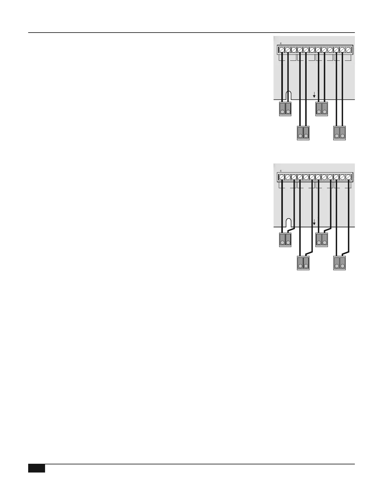
• Terminals C2, C5, C8, and C11 on the Multi-MOD Platinum must be
connected to the modulation Signal (+) terminals on the burners
• Terminals C1, C4, C7, and C10 on the Multi-MOD Platinum must be
connected to the modulation Common terminals on the burners
MULTI-MOD
Platinum
MADE IN U.S.A.
PREV.
(DEL)
SAFETY
GROUND
MUST BE
CONNECTED
OUT
TEMP
PROVE
/DHW
STAGE
A
STAGE
B
MENU FUNCTIONS
SELECT enters menus or accepts changes
ADJUST selects menu items or changes settings
BACK returns to previous menu
PREV./NEXT steps through stage status
DEL deletes schedule settings
STAGE
(DAY)
HELP NEXT
PRESS TO
SELECT
BACK
ADJUST
A1
A2
A3
A4
A5
A6
A7
A8
A9
A10
A11
A12
STAGE
C
DO NOT APPLY ANY VOLTAGE
TO SENSOR TERMINALS
B1
B2
B3
B4
B5
B6
NETWORK
PRESS
4-20 mA
SHUTDOWN
SYSTEM
TEMP
INPUTS
ROUTE SENSOR AND AUXILIARY WIRES
THROUGH THIS KNOCKOUT ONLY
<A> B C D
100% 50% --- ---
T
T
OUTPUT RATINGS:
120VAC, 6A RESISTIVE
1A PILOT DUTY
15A TOTAL
FOR ALL CIRCUITS
INPUT RATINGS:
115VAC 60Hz
30VA MAX
USE COPPER WIRE,
CLASS 1 WIRE ONLY
ENCLOSED
ENERGY
MANAGEMENT
EQUIPMENT
LISTED
99RA
STAGE selects stage menus or next stage
DAY selects next day
SYSTEM B C DA
LINE
NEUTRAL
SYS
B C DA
1 2 3 4
5 6 7 8 9 10 11 12
FULL MODULATION
SEQUENCING CONTROL
LOCKOUT
INPUTS
STAGE
D
B7
B8
OPERATING LIMIT
OUTPUTS
SIGNAL
SHIELD
+
EMS
MODULATION OUTPUTS
A B C
D
C1 C2 C3 C4 C5 C6 C7 C8 C9 C10 C11 C12
Boiler1
4-20mA
Signal
+-
Boiler3
4-20mA
Signal
+-
Boiler2
4-20mA
Signal
+-
Boiler4
4-20mA
Signal
+-
Boiler 4-20mA
Modulation Signal
mA
Com
mA
Com
mA
Com
mA
Com
• The Multi-MOD Platinum can operate up to four voltage-modulating
motors (Multi-MOD ordered with C/V (Current Voltage) output cards) See
"Modulating Output Card Installation" on page 23
• The Multi-MOD Platinum can modulate any of the following voltage motors:
0-10V, 0-5V, 2-10BV, 1-5V See "Output Type" on page 27
• Apply the supplied label marked Current/Voltage below the modulating
terminals
• Terminals C1, C4, C7, and C10 on the Multi-MOD Platinum must be
connected to the modulation Ground terminals on the burners
• Terminals C3, C6, C9, and C12 on the Multi-MOD Platinum must be
connected to the modulation Voltage (V+) terminals on the burners
MULTI-MOD
Platinum
MADE IN U.S.A.
PREV.
(DEL)
SAFETY
GROUND
MUST BE
CONNECTED
OUT
TEMP
PROVE
/DHW
STAGE
A
STAGE
B
MENU FUNCTIONS
SELECT enters menus or accepts changes
ADJUST selects menu items or changes settings
BACK returns to previous menu
PREV./NEXT steps through stage status
DEL deletes schedule settings
STAGE
(DAY)
HELP NEXT
PRESS TO
SELECT
BACK
ADJUST
A1
A2
A3
A4
A5
A6
A7
A8
A9
A10
A11
A12
STAGE
C
DO NOT APPLY ANY VOLTAGE
TO SENSOR TERMINALS
B1
B2
B3
B4
B5
B6
NETWORK
PRESS
4-20 mA
SHUTDOWN
SYSTEM
TEMP
INPUTS
ROUTE SENSOR AND AUXILIARY WIRES
THROUGH THIS KNOCKOUT ONLY
<A> B C D
100% 50% --- ---
T
T
OUTPUT RATINGS:
120VAC, 6A RESISTIVE
1A PILOT DUTY
15A TOTAL
FOR ALL CIRCUITS
INPUT RATINGS:
115VAC 60Hz
30VA MAX
USE COPPER WIRE,
CLASS 1 WIRE ONLY
ENCLOSED
ENERGY
MANAGEMENT
EQUIPMENT
LISTED
99RA
STAGE selects stage menus or next stage
DAY selects next day
SYSTEM B C DA
LINE
NEUTRAL
SYS
B C DA
1 2 3 4
5 6 7 8 9 10 11 12
FULL MODULATION
SEQUENCING CONTROL
LOCKOUT
INPUTS
STAGE
D
B7
B8
OPERATING LIMIT
OUTPUTS
SIGNAL
SHIELD
+
EMS
MODULATION OUTPUTS
A B C
D
C1 C2 C3 C4 C5 C6 C7 C8 C9 C10 C11 C12
Boiler1
Voltage
Signal
+-
Boiler Voltage
Modulation Signal
Boiler3
Voltage
Signal
+-
Boiler2
Voltage
+-
Boiler4
Voltage
+-
V+
GND
V+
GND
V+
GND
V+
GND
• The Multi-MOD Platinum can communicate to and modulate burners
equipped with the Siemens
®
LMV The LMV communicates over Modbus
networks See "Stage Interface" on page 27
• The LMV Interface communicates the boiler modulation from
the Multi-MOD Platinum to the Siemens
®
LMV burner control In
addition, it sends the boiler lockout information from the LMV to the
Multi-MOD Platinum Each burner must be connected to a LMV Interface
The LMV Interface must be purchased separately (HT #926621-00) In
addition, an Interface Power Supply (HT #926622-00) must be purchased
for every 10 LMV Interfaces
• See LMV Interface Manual for information on conguring and wiring to the
Siemens
®
LMV equipped burners