HT# 059299-00 A
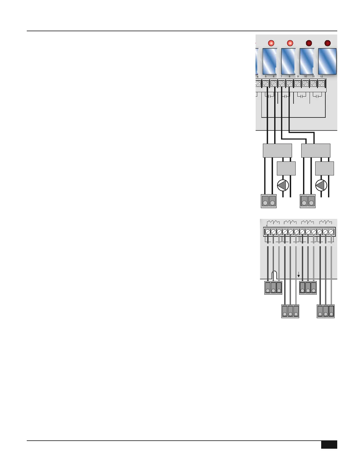
• To have the Multi-MOD Platinum operate the boilers and their pumps, use
SPDT relays (Single-Pole Double-Throw) and TDR relays (Time-Delay
relay)
• The SPDT relay sends the activation signal from the Multi-MOD Platinum
stage activation output to the boiler Interlock (TT) and its pump
• The TDR relay receives the SPDT pump activation signal and send it to the
pump When the SPDT relay signal ends, the TDR keeps the pump running
for an additional period This additional delay acts as the Run-On delay
available for the System output See "System Run-On" on page 34
MULTI-MOD
Platinum
MADE IN U.S.A.
PREV.
(DEL)
SAFETY
GROUND
MUST BE
CONNECTED
OUT
TEMP
PROVE
/DHW
STAGE
A
STAGE
B
MENU FUNCTIONS
SELECT enters menus or accepts changes
ADJUST selects menu items or changes settings
BACK returns to previous menu
PREV./NEXT steps through stage status
DEL deletes schedule settings
STAGE
(DAY)
HELP NEXT
PRESS TO
SELECT
BACK
ADJUST
A1
A2
A3
A4
A5
A6
A7
A8
A9
A10
A11
A12
STAGE
C
DO NOT APPLY ANY VOLTAGE
TO SENSOR TERMINALS
B1
B2
B3
B4
B5
B6
NETWORK
PRESS
4-20 mA
SHUTDOWN
SYSTEM
TEMP
INPUTS
ROUTE SENSOR AND AUXILIARY WIRES
THROUGH THIS KNOCKOUT ONLY
<A> B C D
100% 50% --- ---
T
T
OUTPUT RATINGS:
120VAC, 6A RESISTIVE
1A PILOT DUTY
15A TOTAL
FOR ALL CIRCUITS
INPUT RATINGS:
115VAC 60Hz
30VA MAX
USE COPPER WIRE,
CLASS 1 WIRE ONLY
ENCLOSED
ENERGY
MANAGEMENT
EQUIPMENT
LISTED
99RA
STAGE selects stage menus or next stage
DAY selects next day
SYSTEM B C DA
LINE
NEUTRAL
SYS
B C DA
4
5 6 7 8 9 10 11 12
FULL MODULATION
SEQUENCING CONTROL
LOCKOUT
INPUTS
STAGE
D
B7
B8
OPERATING LIMIT
OUTPUTS
SIGNAL
SHIELD
+
EMS
MODULATION OUTPUTS
A B C
D
C1 C2 C3 C4 C5 C6 C7 C8 C9 C10 C11 C12
S
+
SPDT
Relay 1
Boiler
Activation
Boiler1 Pump1
TDR
Relay 1
L N
120VAC
SPDT
Relay 2
TDR
Relay 2
L N
120VAC
• The Multi-MOD Platinum can operate up to four 135 Ω modulating motors
(Multi-MOD ordered with 135-Ohm Output cards) Each 135 Ohm Output
card operates two stages See "Modulating Output Card Installation" on
page 23
• Terminals C1, C4, C7, and C10 on the Multi-MOD Platinum connects to the
modulation decreasing terminals on the burners (Blue/Black modulating
wires)
• Terminals C3, C6, C9, and C12 on the Multi-MOD Platinum connects to the
modulation increasing on the burners (White modulating wires)
• Terminals C2, C5, C8, and C11 on the Multi-MOD Platinum connects to the
modulation common terminals on the burners (Red modulating wires)
MULTI-MOD
Platinum
MADE IN U.S.A.
PREV.
(DEL)
SAFETY
GROUND
MUST BE
CONNECTED
OUT
TEMP
PROVE
/DHW
STAGE
A
STAGE
B
MENU FUNCTIONS
SELECT enters menus or accepts changes
ADJUST selects menu items or changes settings
BACK returns to previous menu
PREV./NEXT steps through stage status
DEL deletes schedule settings
STAGE
(DAY)
HELP NEXT
PRESS TO
SELECT
BACK
ADJUST
A1
A2
A3
A4
A5
A6
A7
A8
A9
A10
A11
A12
STAGE
C
DO NOT APPLY ANY VOLTAGE
TO SENSOR TERMINALS
B1
B2
B3
B4
B5
B6
NETWORK
PRESS
4-20 mA
SHUTDOWN
SYSTEM
TEMP
INPUTS
ROUTE SENSOR AND AUXILIARY WIRES
THROUGH THIS KNOCKOUT ONLY
<A> B C D
100% 50% --- ---
T
T
OUTPUT RATINGS:
120VAC, 6A RESISTIVE
1A PILOT DUTY
15A TOTAL
FOR ALL CIRCUITS
INPUT RATINGS:
115VAC 60Hz
30VA MAX
USE COPPER WIRE,
CLASS 1 WIRE ONLY
ENCLOSED
ENERGY
MANAGEMENT
EQUIPMENT
LISTED
99RA
STAGE selects stage menus or next stage
DAY selects next day
SYSTEM B C DA
LINE
NEUTRAL
SYS
B C DA
1 2 3 4
5 6 7 8 9 10 11 12
FULL MODULATION
SEQUENCING CONTROL
LOCKOUT
INPUTS
STAGE
D
B7
B8
OPERATING LIMIT
OUTPUTS
SIGNAL
SHIELD
+
EMS
MODULATION OUTPUTS
A B C
D
C1 C2 C3 C4 C5 C6 C7 C8 C9 C10 C11 C12
Boiler1
135Ω
Signal
B R W
Boiler2
135Ω
Signal
B R W
Boiler4
135Ω
Signal
B R W
Boiler3
135Ω
Signal
B R W
Boiler 135Ω
Modulation Signal
B R W R W R W R WB B B
• The Multi-MOD Platinum can operate up to four 4-20 mA modulating
motors (Multi-MOD ordered with C/V (Current/Voltage) output cards) See
"Modulating Output Card Installation" on page 23
• To program the control for 4-20 mA output, See "Output Type" on page 27
• Apply the supplied label marked Current/Voltage below the modulating
terminals
• The Multi-MOD sources 24VDC excitation voltage for the 4-20mA signal