HT# 059299-00 A
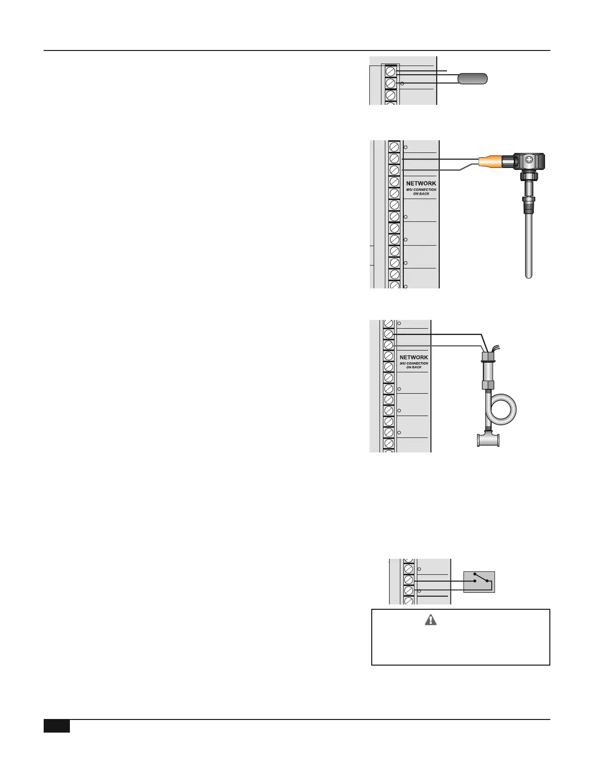
• Attach the sensor wires to the Out Temp terminals (A11 and A12)
Temperature sensors have no polarity
• Connect the shield to terminal A12 with one of the other sensor
wires Do not connect the shield at the sensor end
• The sensor wires can be extended up to 500’ using shielded
2-conductor cable (#18/2)
MULTI-MOD
Platinum
MADE IN U.S.A.
PREV.
(DEL)
SAFETY
GROUND
MUST BE
CONNECTED
OUT
TEMP
PROVE
/DHW
STAGE
A
STAGE
B
MENU FUNCTIONS
SELECT enters menus or accepts changes
ADJUST selects menu items or changes settings
BACK returns to previous menu
PREV./NEXT steps through stage status
DEL deletes schedule settings
STAGE
(DAY)
HELP NEXT
PRESS TO
SELECT
BACK
ADJUST
A1
A2
A3
A4
A5
A6
A7
A8
A9
A10
A11
A12
STAGE
C
DO NOT APPLY ANY VOLTAGE
TO SENSOR TERMINALS
B1
B2
B3
B4
B5
B6
NETWORK
PRESS
4-20 mA
SHUTDOWN
SYSTEM
TEMP
INPUTS
ROUTE SENSOR AND AUXILIARY WIRES
THROUGH THIS KNOCKOUT ONLY
<A> B C D
100% 50% --- ---
T
T
OUTPUT RATINGS:
120VAC, 6A RESISTIVE
1A PILOT DUTY
15A TOTAL
FOR ALL CIRCUITS
INPUT RATINGS:
115VAC 60Hz
30VA MAX
USE COPPER WIRE,
CLASS 1 WIRE ONLY
ENCLOSED
ENERGY
MANAGEMENT
EQUIPMENT
LISTED
99RA
STAGE selects stage menus or next stage
DAY selects next day
SYSTEM B C DA
LINE
NEUTRAL
SYS
B C DA
1 2 3 4
5 6 7 8 9 10 11 12
FULL MODULATION
SEQUENCING CONTROL
LOCKOUT
INPUTS
STAGE
D
B7
B8
OPERATING LIMIT
OUTPUTS
SIGNAL
SHIELD
+
EMS
MODULATION OUTPUTS
A B C
D
C1 C2 C3 C4 C5 C6 C7 C8 C9 C10 C11 C12
S
+
Shield
System
Temperature
Sensor
TGT= 126
o
F
SYS= 125
o
F OD= 31
o
F
• The Multi-MOD Platinum can connect to a 4-20mA temperature
sensor (HT# 904160-00) See "Sensor Type" on page 26
• Locate the temperature sensor on the main supply header where
it will register the output of all the stages If the sensor cannot
read the output of all the stages, the Multi-MOD Platinum will not
be able to control the stages properly
• 4-20mA Temperature Sensor wires can be extended up to 500' by
splicing with 18 gauge twisted pair wire
• Connect the sensor's Blue wire to terminal PRESS - A5 (S)
• Connect the sensor's Brown wire to terminal PRESS - A6 (+)
• Cut the rest of the transducer wires and tubes
MULTI-MOD
Platinum
MADE IN U.S.A.
PREV.
(DEL)
SAFETY
GROUND
MUST BE
CONNECTED
OUT
TEMP
PROVE
/DHW
STAGE
A
STAGE
B
MENU FUNCTIONS
SELECT enters menus or accepts changes
ADJUST selects menu items or changes settings
BACK returns to previous menu
PREV./NEXT steps through stage status
DEL deletes schedule settings
STAGE
(DAY)
HELP NEXT
PRESS TO
SELECT
BACK
ADJUST
A1
A2
A3
A4
A5
A6
A7
A8
A9
A10
A11
A12
STAGE
C
DO NOT APPLY ANY VOLTAGE
TO SENSOR TERMINALS
B1
B2
B3
NETWORK
PRESS
4-20 mA
SHUTDOWN
SYSTEM
TEMP
INPUTS
ROUTE SENSOR AND AUXILIARY WIRES
THROUGH THIS KNOCKOUT ONLY
<A> B C D
100% 50% --- ---
T
T
OUTPUT RATINGS:
120VAC, 6A RESISTIVE
1A PILOT DUTY
15A TOTAL
FOR ALL CIRCUITS
INPUT RATINGS:
115VAC 60Hz
30VA MAX
USE COPPER WIRE,
CLASS 1 WIRE ONLY
ENCLOSED
ENERGY
MANAGEMENT
EQUIPMENT
LISTED
99RA
STAGE selects stage menus or next stage
DAY selects next day
SYSTEM B C DA
LINE
NEUTRAL
SYS
B C DA
1 2 3 4
5 6 7 8 9 10 11 12
FULL MODULATION
SEQUENCING CONTROL
LOCKOUT
INPUTS
STAGE
D
B7
B8
OPERATING LIMIT
OUTPUTS
SIGNAL
SHIELD
+
EMS
MODULATION OUTPUTS
A B C
D
C1 C2 C3 C4 C5 C6 C7 C8 C9 C10 C11 C12
S
+
TGT= 5 PSI
SYS= 4 PSI OD= 31
o
F
Brown (+)
Blue (-)
• The Multi-MOD Platinum is designed to connect to a pressure
transducer See "Sensor Type" on page 26
• Locate the transducer on the main supply header where it will
register the output of all the stages If the transducer cannot read
the output of all the stages, the Multi-MOD Platinum will not be
able to control the stages properly
• Attach the transducer to the steam header using a ¼" isolation
tube (pigtail) (HT# 135020-00)
• Pressure transducer wires can be extended up to 500' by splicing
with 18 gauge twisted pair wire
• Connect the Black wire from the pressure transducer to terminal
PRESS - A5 (S)
• Connect the Red wire from the pressure transducer to terminal
PRESS - A6 (+)
• Cut the rest of the transducer wires and tubes
MULTI-MOD
Platinum
MADE IN U.S.A.
PREV.
(DEL)
SAFETY
GROUND
MUST BE
CONNECTED
OUT
TEMP
PROVE
/DHW
STAGE
A
STAGE
B
MENU FUNCTIONS
SELECT enters menus or accepts changes
ADJUST selects menu items or changes settings
BACK returns to previous menu
PREV./NEXT steps through stage status
DEL deletes schedule settings
STAGE
(DAY)
HELP NEXT
PRESS TO
SELECT
BACK
ADJUST
A1
A2
A3
A4
A5
A6
A7
A8
A9
A10
A11
A12
STAGE
C
DO NOT APPLY ANY VOLTAGE
TO SENSOR TERMINALS
B1
B2
B3
NETWORK
PRESS
4-20 mA
SHUTDOWN
SYSTEM
TEMP
INPUTS
ROUTE SENSOR AND AUXILIARY WIRES
THROUGH THIS KNOCKOUT ONLY
<A> B C D
100% 50% --- ---
T
T
OUTPUT RATINGS:
120VAC, 6A RESISTIVE
1A PILOT DUTY
15A TOTAL
FOR ALL CIRCUITS
INPUT RATINGS:
115VAC 60Hz
30VA MAX
USE COPPER WIRE,
CLASS 1 WIRE ONLY
ENCLOSED
ENERGY
MANAGEMENT
EQUIPMENT
LISTED
99RA
STAGE selects stage menus or next stage
DAY selects next day
SYSTEM B C DA
LINE
NEUTRAL
SYS
B C DA
1 2 3 4
5 6 7 8 9 10 11 12
FULL MODULATION
SEQUENCING CONTROL
LOCKOUT
INPUTS
STAGE
D
B7
B8
OPERATING LIMIT
OUTPUTS
SIGNAL
SHIELD
+
EMS
MODULATION OUTPUTS
A B C
D
C1 C2 C3 C4 C5 C6 C7 C8 C9 C10 C11 C12
S
+
Cut the rest of
Connect to
1/4" pigtail
Black (-)
Red (+)
Transducer
4-20mA
TGT= 5 PSI
SYS= 4 PSI OD= 31
o
F
• The Shutdown is used to turn off the control remotely It can be
congured for Normally Open (Shutdown) or Normally Closed
(TSTAT)
• If boilers are running and he shutdown termnal is closed remotely
all active stages will modulate down to low re (Ignition %) They
will remain there until the adjustable Soft-Off period has nished
See page 37 for Soft-Off
• The System output will remain active until the Run-On Delay
ends, then it will also turn off See "System Run-On" on page 34
MULTI-MOD
Platinum
MADE IN U.S.A.
PREV.
(DEL)
SAFETY
GROUND
MUST BE
CONNECTED
OUT
TEMP
PROVE
/DHW
STAGE
A
STAGE
B
MENU FUNCTIONS
SELECT enters menus or accepts changes
ADJUST selects menu items or changes settings
BACK returns to previous menu
PREV./NEXT steps through stage status
DEL deletes schedule settings
STAGE
(DAY)
HELP NEXT
PRESS TO
SELECT
BACK
ADJUST
A1
A2
A3
A4
A5
A6
A7
A8
A9
A10
A11
A12
STAGE
C
DO NOT APPLY ANY VOLTAGE
TO SENSOR TERMINALS
B1
B2
B3
B4
B5
B6
NETWORK
PRESS
4-20 mA
SHUTDOWN
TEMP
INPUTS
ROUTE SENSOR AND AUXILIARY WIRES
THROUGH THIS KNOCKOUT ONLY
<A> B C D
100% 50% --- ---
T
T
OUTPUT RATINGS:
120VAC, 6A RESISTIVE
1A PILOT DUTY
15A TOTAL
FOR ALL CIRCUITS
INPUT RATINGS:
115VAC 60Hz
30VA MAX
USE COPPER WIRE,
CLASS 1 WIRE ONLY
ENCLOSED
ENERGY
MANAGEMENT
EQUIPMENT
LISTED
99RA
STAGE selects stage menus or next stage
DAY selects next day
SYSTEM B C DA
LINE
NEUTRAL
SYS
B C DA
1 2 3 4
5 6 7 8 9 10 11 12
FULL MODULATION
SEQUENCING CONTROL
LOCKOUT
INPUTS
STAGE
D
B7
B8
OPERATING LIMIT
OUTPUTS
SIGNAL
SHIELD
+
EMS
MODULATION OUTPUTS
A B C
D
C1 C2 C3 C4 C5 C6 C7 C8 C9 C10 C11 C12
S
Shutdown
Dry Contact
To avoid damage to the Multi-MOD,
NO VOLTAGE can be applied to the
Multi-MOD Platinum input terminals