HT# 059299-00 A
• The 4-20ma option is used with the 4-20mA temperature sensor
(HT# 904160-00) These sensors can be congured to read temperatures
up to 480°F / 268°C The user must set the 4ma and 20ma temperature
range to match the sensor conguration These sensors' ranges must be
set by Heat-Timer See "4-20mA Temperature Sensor Wiring" on page 18
• Values that are higher than 216mA shall read SHORT Values that are
lower than 24mA shall read OPEN
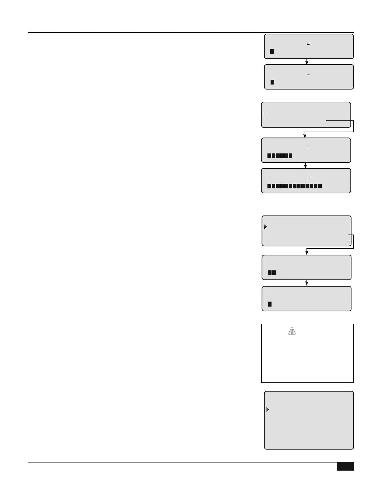
SENSOR 4mA VALUE
0
F
[
]
SENSOR 20mA VALUE
0
F
[ ]
/<System Startup>/..../Sensor Type/EMS Input Mode/ EMS 4mA SP/..
• Setback allows the Set Point to be adjusted manually
• EMS Control allows the set point to be sent remotely using 4-20mA
signal The set point range must be set to match the EMS signal's set
point range using the 4mA and the 20mA temperature settings See
"External Set Point Wiring" on page 22
• An active signal must be between 2 and 22mA Any signal out of this
range shuts down the system and displays "Shutdown by EMS"
EMS 4mA SETPOINT
140
F
[
]
EMS 20mA SETPOINT
200
F
[
]
- EMS INPUT MODE -
Setback
EMS Control
/<System Startup>/.../Stage Interface/ Stage A Modbus Add/ ...
• These options are designed for Modbus operating burners equipped
with the Siemens LMV controller If the burner did not have Modbus
communication, then select Normal
• The MODBUS-Monitor Only option receives the alarm lockout status
through the Siemens LMV Interface
• The MODBUS-Full Control option sends the modulation percent and
receives the lockout status through the Siemens LMV Interface
• Order the LMV Interface for each of the MODBUS burners
(HT# 926621-00) In addition, order the Interface Power Supply
(HT #926622-00) for every 10 burners See LMV-Interface Manual
• When any of the Modbus options is selected from the Stage Interface
menu, the Stage Modbus Address will follow
• Each Stage address must be unique on the Modbus network
• To exit the Stage Modbus Address, enter an address of 0 for the stage
following the last stage
STAGE A MODBUS ADD
1
[
]
STAGE B MODBUS ADD
0
[
]
- STAGE INTERFACE -
Normal
MODBUS-Monitor Only
MODBUS-Full Control
Regardless of the Modbus
options selected, the
Multi-MOD Platinum will also
send a modulation signal to
every active boiler through the
Modulation Output terminals
/<System Startup>/ Sensor Type/.../Output Type A&B
• The Multi-MOD Platinum has two Modulating Output Cards Each card
modulates two stages Both stages must use the same modulating
signal See "Modulating Output Card Installation" on page 23
• Output Cards can be either 135Ω Cards for 135 ohm modulating motors
or Current/Voltage Cards for current or voltage signal operating motors
-OUTPUT TYPE A&B-
Not Installed
135ohm
0-10v
0-5v
2-10v
1-5v
4-20ma