 Loading...
Do you have a question about the Hexagon Absolute Arm RS5 and is the answer not in the manual?
| Number of Axes | 7 |
|---|---|
| Protection Rating | IP54 |
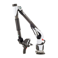
| Type | Articulated Arm |
| Articulating Arm Length | Up to 5 meters |
| Scanning Technology | Laser Line Scanning |
| Connectivity | USB, Wi-Fi |
| Software Compatibility | PolyWorks, Metrolog X4 |
Details safety precautions for mechanical hazards like pinch points, counterweights, and arm installation.
Outlines critical safety warnings regarding battery handling, transport, and potential hazards.
Provides essential safety guidelines for using power supply cords and avoiding electrical hazards.
Warns about potential eye injury from laser guides and advises caution with laser equipment.
Describes the various components of the Absolute Arm, including its structure and key parts.
Details the Base and Control Pack components, including front and back panel descriptions.
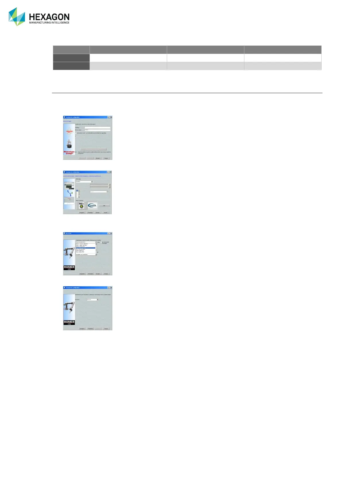
Provides step-by-step instructions for installing the RDS software package on a computer.
Explains various mounting possibilities and base options for the Absolute Arm.
Provides recommendations and procedures for handling and installing the Absolute Arm.
Guides through the process of setting up a USB connection for the arm, excluding scanners.
Details the USB connection procedure for the arm when using an integrated scanner.
Explains how to establish a wireless Wi-Fi connection for the arm and scanners.
Guides the user through setting up an Ethernet connection for the arm and scanners.
Covers the use of contact probes, including recognition, alignment, and probing techniques.
Explains the importance and methods for verifying the arm's accuracy and calibration periodically.