4.1 Control Box
Chapter 4: Removal, Replacement, and Adjustment Procedures
Page 4 - 2 Electrically Operated General Ward Bed
Operation and Maintenance Manual (154588 REV 1)
4.1 Control Box
Tools required: Screwdriver
#2 phillips screwdriver
11 mm spanner wrench
Removal
Failure to unplug the unit from its power source could cause injury or
equipment damage.
1. Unplug the mains power.
2. Lock all functions at the attendant control panel.
3. Set the brakes.
4. Lift the backrest to have access to the control box.
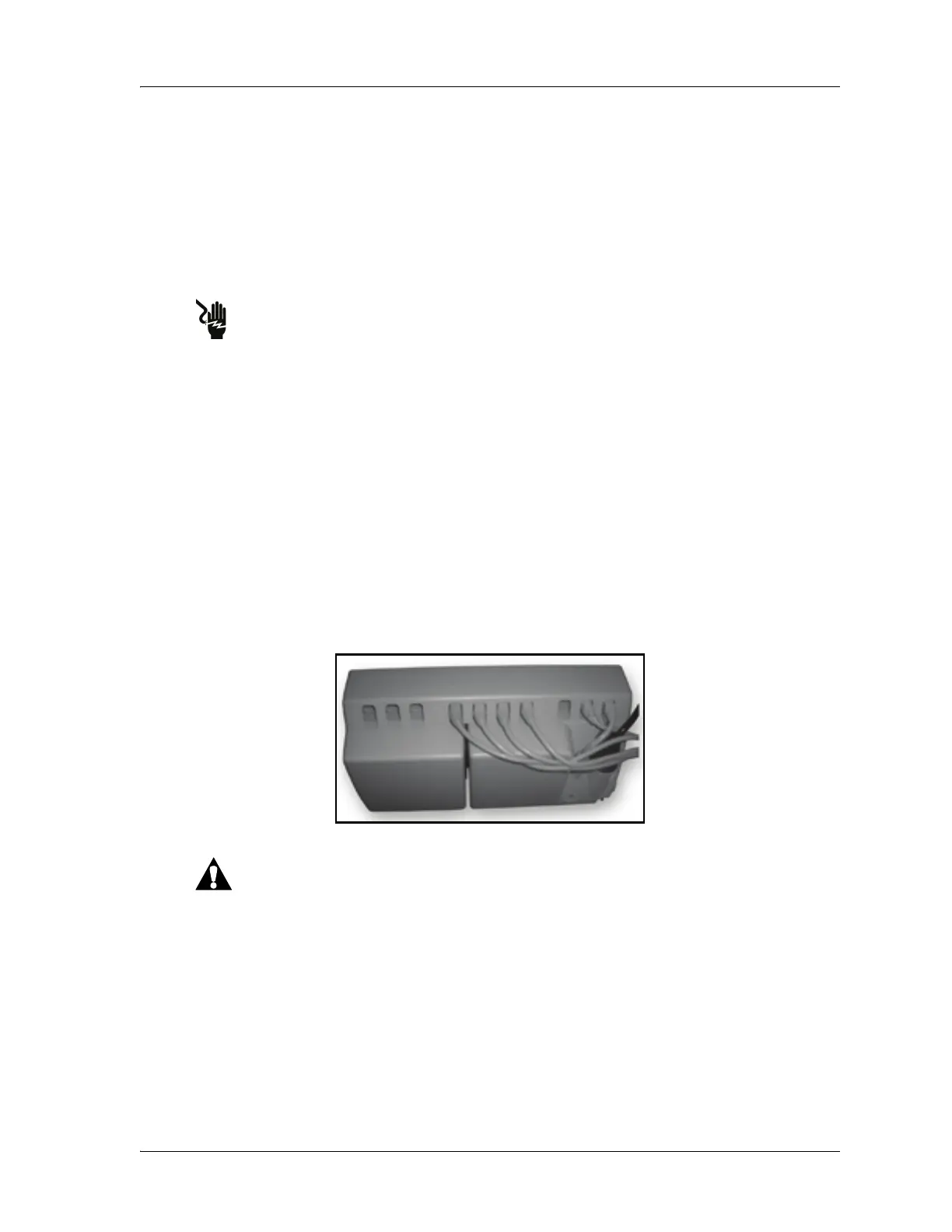
5. Remove the control box socket cover to access the connection ports (see
figure 4-1 on page 4-2).
Figure 4-1. Connection Ports
Label the cables before they are disconnected to make sure they are
reconnected in the correct locations on the new control box. Failure to
reconnect the cables to the same/correct ports can cause damage to
the electrical system.
6. Label and disconnect all cables on the control box.
 Loading...