4.1 Control Box
Chapter 4: Removal, Replacement, and Adjustment Procedures
Electrically Operated General Ward Bed Page 4 - 3
Operation and Maintenance Manual (154588 REV 1)
4
Support the control box. Failure to support the control box as the
fasteners are removed will cause damage to the plastic housing and
void the warranty.
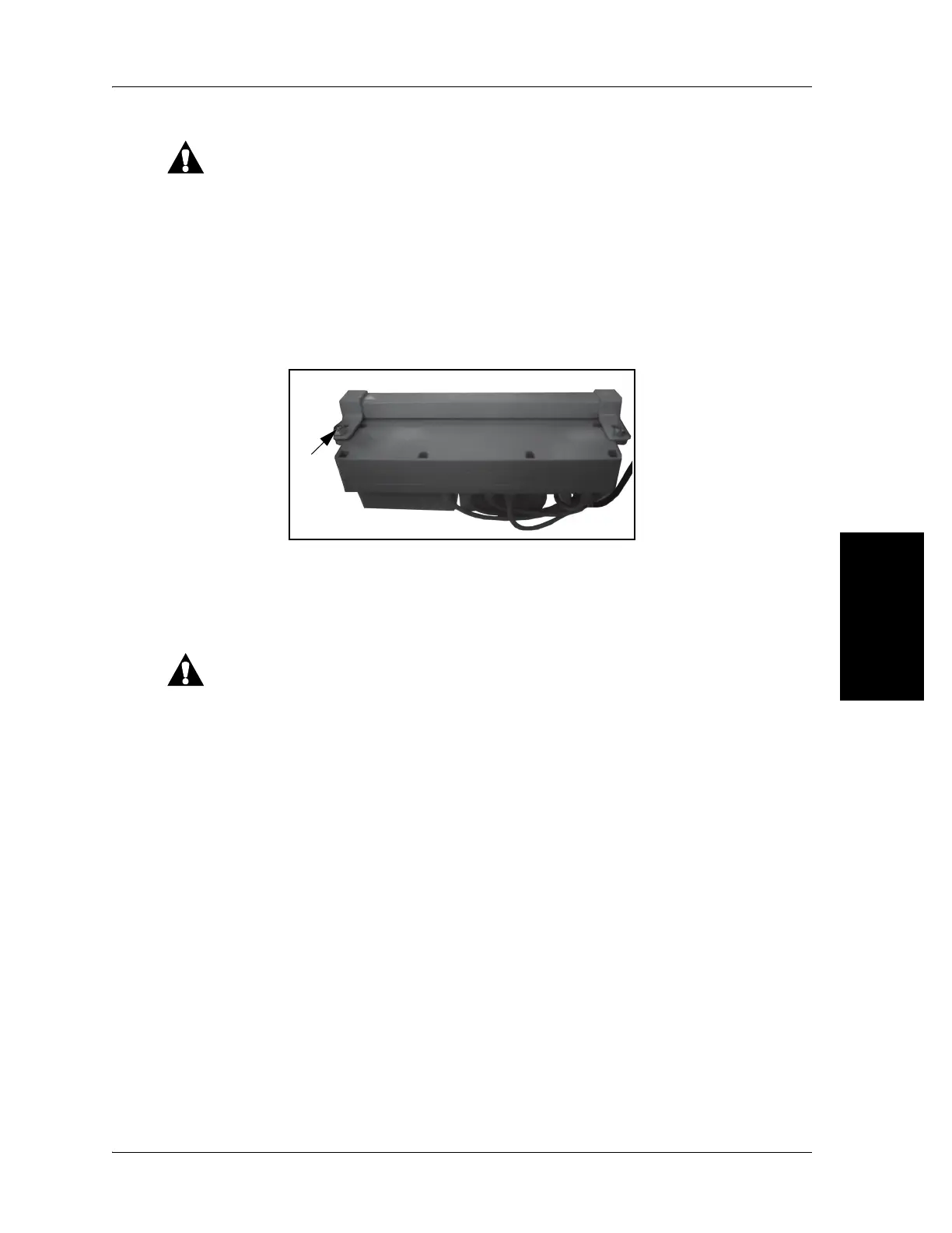
7. Support the control box and remove the four fasteners (A) that secure the
control box to the bed frame (see figure 4-2 on page 4-3). (There are two
fasteners for each bracket.)
Figure 4-2. Control Box Fasteners
Replacement
1. Reverse this procedure to install the control box.
Cable routing, clamps, and cable ties must be replaced as per the
original installation. Failure to install items correctly can cause damage
to the cables.
2. Do the “Function Checks” on page 2-3.
 Loading...