4.5 Castor
Chapter 4: Removal, Replacement, and Adjustment Procedures
Electrically Operated General Ward Bed Page 4 - 15
Operation and Maintenance Manual (154588 REV 1)
4
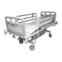
– Tracking castors are identified by a black ring at the top of the castor
stem (see figure 4-16 on page 4-15).
Figure 4-16. Tracking Castor
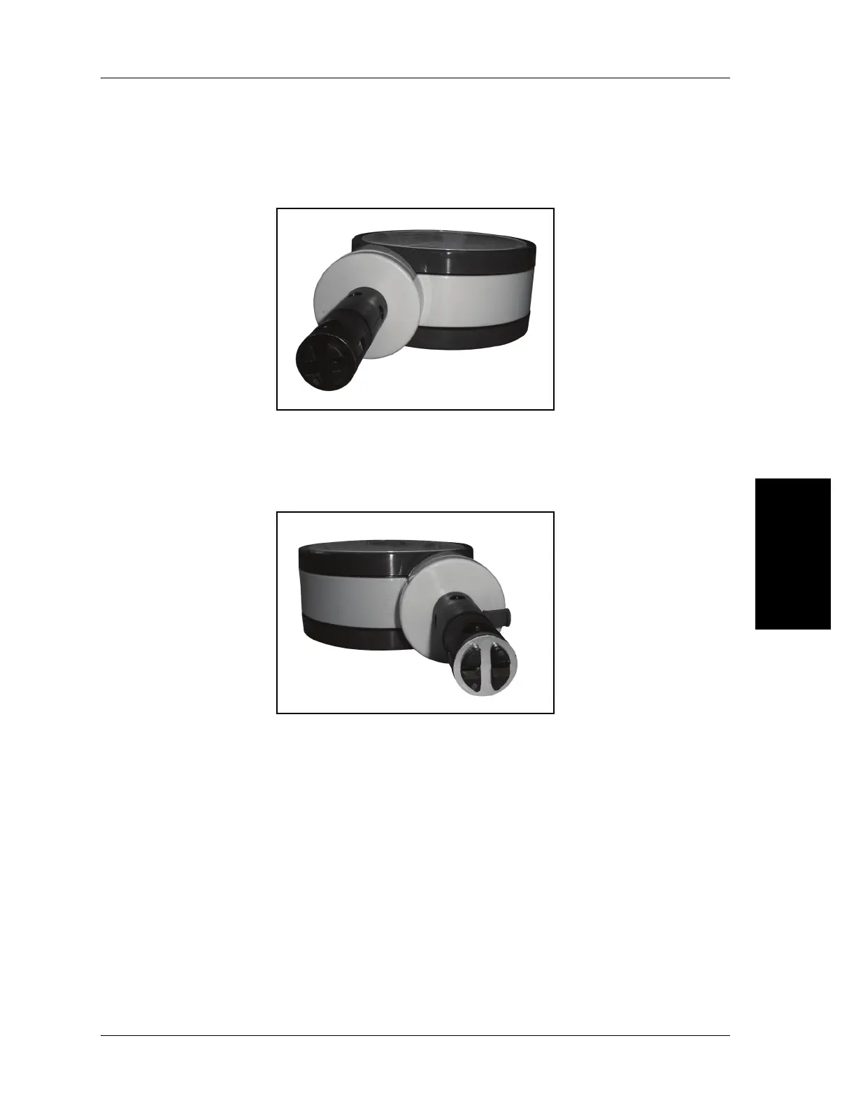
– Brake castors are identified by a silver ring at the top of the castor
stem (see figure 4-17 on page 4-15).
Figure 4-17. Brake Castor
Each bed has one tracking castor (on the patients LH side of the head end of
the bed) and three brake castors.
Replacement
Make sure that the replacement castor is the same type as the castor being
replaced.
1. Put the new castor in the neutral position.
 Loading...