Installation BRS20/30/40/50
Release
02
11/2018
23
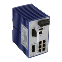
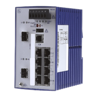
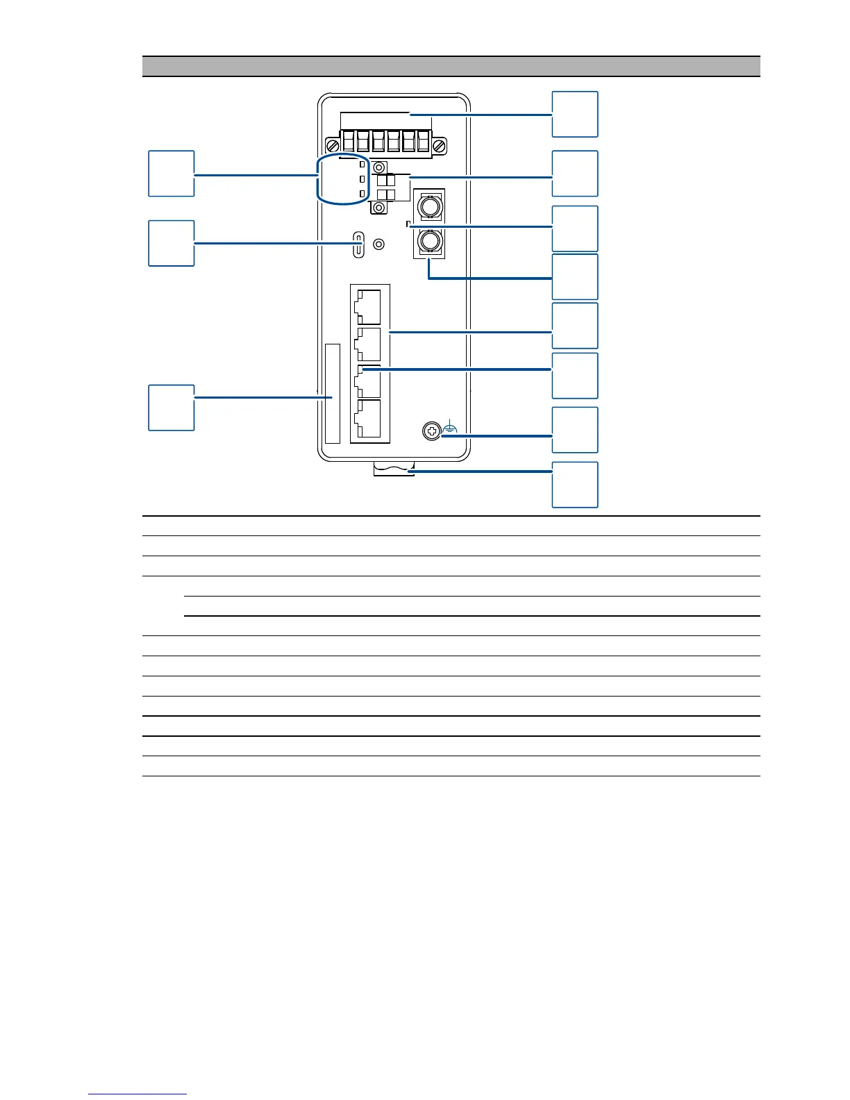
BRS20-0500xx99-xxC...
1 6-pin terminal block with screw lock for redundant power supply and signal contact
2 2-pin terminal block with screw lock for the digital input
3 LED display elements for port status
4 depending on device variant
DSC or DST singlemode socket for 100 Mbit/s fiber optic connections
DSC or DST multimode socket for 100 Mbit/s fiber optic connections
5 4 × RJ45 socket for 10/100 Mbit/s Twisted pair connections
6 LED display elements for port status
7 Grounding screw
8 Rail lock slide for DIN rail mounting
9 Label area for IP address of device
10 USB-C interface
11 LED display elements for device status
 Loading...