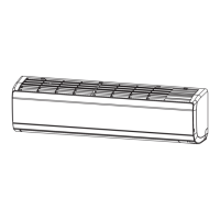
9.7 OPERATION WITH WIRED REMOTE CONTROL SWITCH
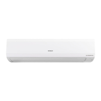
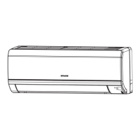
The indoor unit can be operated by both wired and wireless
remote control switches. Contact your distributor and contractor
for detail.
Wired remote
control switch
(PC-ARF**)
Wireless remote
control switch
(PC-AWR)
9.8 AUTOMATIC OPERATION
Refer to the installation and operation manual of the indoor unit.
9.9 OPTIONAL FUNCTIONS FOR RECEIVER KIT
! DANGER
TurnOFFthepowersourcecompletelybeforeperformingthedipswitchsettingforreceiverkit.Ifnot,itmaycauseanelectricshock.
1 The following switches are on the receiver kit.
Emergency
CoolHeat
RunFilter DefTimer
123456
ON
Switch "Heat" Switch "Cool"
Remove the
screw
Rear side of
receiver kit
Dip switch (DSW1)
(Factory-setting)
CoverPCB
2 Emergency operation setting
“Cool” and “Heat” switches are used for emergency
operation when the batteries for wireless remote control
switch are shortage.
a. Switch “Cool”: press “Cool” so that the cooling operation
is started.
Press “Cool” again so that the cooling operation is
stopped.
b. Switch “Heat”: press “Heat” so that the heating operation
is started.
Press “Heat” again so that the heating operation is
stopped.
? NOTE
Duringtheemergencyoperation,“ ”lamp(yellow)ashes(0.5second
ON/0.5secondOFF).Thesettingtemperatureandthefan speed for
cooling/heating operation are the same as before starting emergency
operation.
3 The dip switch (DSW1) is for the optional function selection.
If the optional function selection is required, set the DIP
switch as follows.
AIR PANEL P-AP56NAMR
PMML0570 rev.0 - 01/2021
19
EN
 Loading...


