1-38 ● Connection of signals
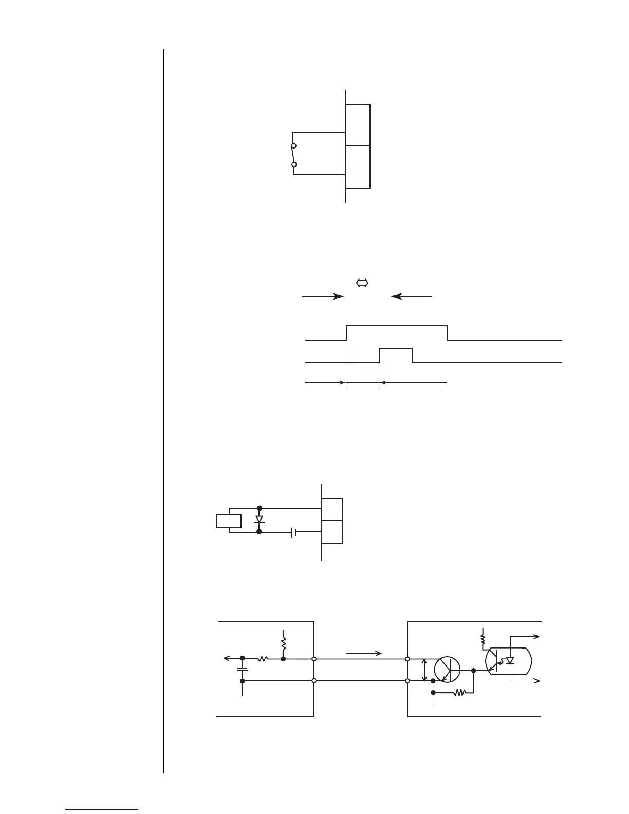
1.5.3-7 Reciprocative printing signal (input)
The following shows the connection terminal for the signal that delivers instructions
for a change in the order of characters to be printed.
(No-voltage contact)
A current of about 12 mA
flows.
9
11
TB1
GND
Signal
Input specifications
●A no-voltage contact must be used for
input.
●In the case of noncontact, the following
requirements must be met.
Withstanding voltage : 12 VDC or more
Maximum drive current : 12 mA or more
Residual voltage : 2 V or less
Leak current : 0.1 mA or less
Drive method : Open collector
When the input is OFF: Forward transport
When the input is ON: Backward transport
(Example)
OFF state
1 2 3
ON state
1 2 3
(The arrow indicates
the sequence of printing.)
Reverse direction printing signal
OFF
ON
OFF
ON
Print object detection signal
100 ms min.
* Ensure that the interval between reciprocative printing signal changeover
(ON→OFF or OFF→ON) and print object detection signal input is at
least 100 ms.
1.5.3-8 Print output signal (output)
The following shows the wiring of the signal that is outputted when a printing
operation is being conducted or completed by the IJ printer.
(a) Wiring
Load
TB1
12
13
Print output
GND
● If a relay, solenoid, or other inductive load is employed, connect a
counterelectromotive force generation prevention diode in parallel with the load.
● The load circuit is for DC only. It cannot be used with an AC load.
Output specifications
Vd
GND
External device
TB1
IL
12
13
V
CE
GND
Tr
+12V
IJ printer
● The output transistor (Tr) is of an open collector type. It operates as indicated below.
While printing is performed (printing-completed signal ON) : Tr ON
While no printing is performed (printing-completed signal OFF) : Tr OFF