Remove four (4) screws which fix the motor.
6 Reassemble the parts in the reverse order of removing procedures.
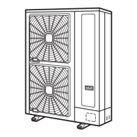
Model RAS-8/10HRNSE
Fan Motor Comp. Nº
DC Fan Motor
PCB5
PCN203 (White)
CN201 (White)
AC Fan Motor
PCB3
PCN404 (White)
Screw for motor
fixing.
DC Fan Motor 4 x M6 screw (with spacer)
AC Fan Motor 4x M6 screws
Motor clamp and wiring fixing position
1. Motor clamp.
2. Fan motor lead wire.
3. Plastic tie.
4. DC Fan Motor.
5. AC Fan Motor.
N O T E
1 The motor lead wires must be through the route as shown in the figure. If not, it may cause the disconnection
to the fan motor lead wires.
2 When mounting the motor, ensure the cables point directly downward. Fix the protection tube edge downward
to ensure the water may not keep in it.
(Adjust the clearance between shroud and propeller fan so that they do not contact.)
3 Fix the motor wires onto the motor clamp with a plastic tie to prevent them from obstructing the propeller fans.
4 Mounting Propeller Fan.
Insert the skidding protection part of fan boss in accordance with the cutting part of the motor shaft, and fix
the screw after exserting screw part of the shaft. (Tightening Torque of 20 Nm).
5 When connecting the motor wire, check to ensure that the colors of the connectors on the PCB3 and PCB5 are
matched with wires.
10 Servicing
417
SMGB0060 rev. 1- 12/2010
10

 Loading...


