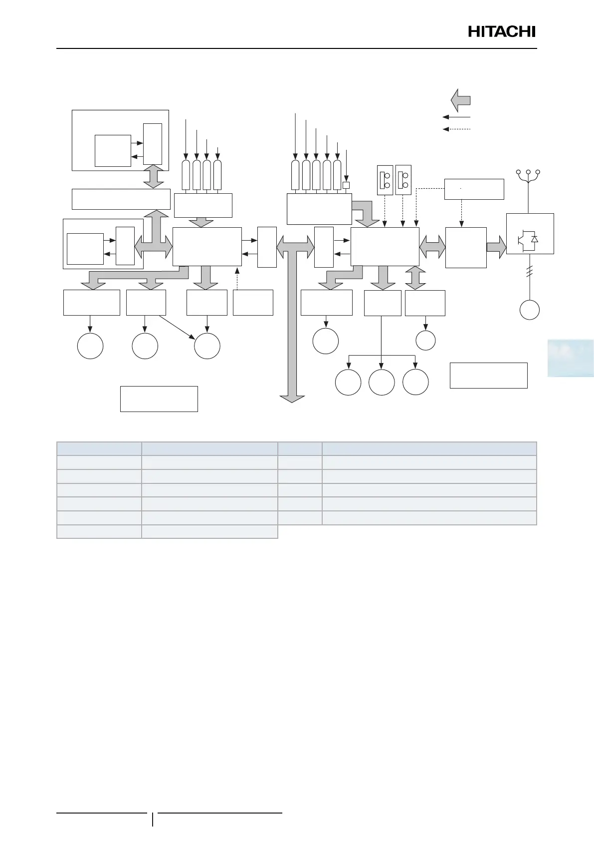
5 Control System
Device control system
SMGB0136 rev.0 - 07/2021
83
5
The gure below shows the outline of the control system for RAS-(4-6)H(R/N)(C/P)2E
Transmission
circuit
Remote
control MCU
Wireless remote control switch
Wireless transmission circuit
A+D conversion
circuit
Thermistor for inlet air
Thermistor of discharge air
Thermistor for gas pipe
Thermistor for liquid pipe
Suction gas pressure sensor
Discharge gas pressure sensor
Thermistor for outdoor temperature
Discharge gas thermistor
Thermistor for heating evaporation temperature
Protection circuit
Inverter
control
MCU
Inverter power
section
MC
Outdoor unit
MCU
Relay drive
circuit
Electrical control
expansion valve
drive circuit
Transmission
circuit
Transmission
circuit
Protective
circuit
Fan control
Indoor unit MCU
Transmission
circuit
Relay drive
circuit
Electrical control
expansion valve
drive circuit
Remote
control
MCU
Remote control switch
CH1
MV
RVR
SVA
MV
MS
MIF
Indoor unit
Outdoor unit
Multiple signals
Single signals
Operation signals
To the transmission of the next indoor
unit or the next outdoor unit (H-LINK)
PSC
A+D conversion
circuit
MOF
Power source
PSH
Inverter
control for fan
MCU
Discharge Gas Pressure Sensor (Pd)
Symbol Description Symbol Description
MC Motor (for compressor) CH Crankcase heater
MIF Motor (for indoor fan) RVR 4-Way valve
MOF Motor (for outdoor fan) SVA Solenoid valve
MS Motor (for auto-louver) PSC Low Pressure switch for control
MV Electronic expansion valve PSH High Pressure switch
CMC Compressor magnetic contactor