6 Optional functions
RAS-3HVRC2
SMGB0136 rev.0 - 07/2021
108
6.1.2.2 Setting of external input and output
If the initial setting has to be modied, the following instructions must be followed:
1 DSW301 PIN4 of the outdoor unit PCB must be set to “ON” before the modication in order to prevent activation of
the compressor. (The setting must be carried out during the stoppage of the outdoor unit.)
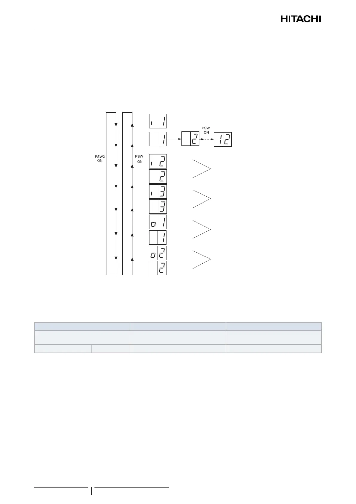
2 Set DSW2 PIN6 ON for “External Input and Output Setting”, it will be displayed on the 7-segment display.
3 Pressing PSW2 and PSW3 changes the input/output terminal name. After the each input/output name appear the
function number, pressing PSW1 it can be changed.
3
1
Input setting 2
Input setting 3
Output setting 1
Output setting 2
Input setting 1
Function
I/O terminal
name
Function
I/O terminal
name
Function
I/O terminal
name
Function
I/O terminal
name
Function
Switch setting
contents with
PSW1
4 After selecting the control function number, turn OFF DSW2 PIN6. The display will be back to the normal operation.
Then turn OFF the DSW301 PIN4. The selected data is stored in the outdoor unit PCB1 and the “External Input and
Output Setting” is completed. The stored data is maintained even when the power source is cut OFF. Refer to the
next table for the details for the electrical wiring connection and the required parts.
Specications of required main parts
Components Specications Remarks
3-pin connector cable
PCC-1A (Accesory)
(connected to a JST Connector, XARP-3)
5 cables with connectors in a single
assembly
Cable (Inside the unit) Low voltage 0.3 mm
2
Less than 24 V
? NOTE
• Theterminalcablemustbeasshortaspossible.
• Donotplacethecablesalongsidethehighvoltagecables.Maintainatleast30cmofdistancebetweenthecableandthehighvoltage
cable.Thecablesmaybecrossed.Ifnecessarytoplacethecablesalongsidethehighvoltagecable,insertthelowvoltagecables
insideametalconduitandgrounditoneoftheend.Ifsealedcablesareusedforthelowvoltagecables,grounditoneoftheendof
theshieldcable.
• Themaximumlengthmustbewithin70m.
6.1.2.3 Optional external output signals
Output signals through 7-segment display
The system has several input and output signals, which can be selected using the following connectors of the PCB:
• Output connector CN7, which has two ports to congure two optional output signals.
The selection of these input and output signals represents the selection of some optional functions programmed in the
PCB through the 7-segment display.