11 Maintenance notes
Refrigerant collection method
SMGB0136 rev.0 - 07/2021
334
11.6 Refrigerant collection method
11.6.1 Refrigerant collection method when replacing the parts of outdoor unit
Process
No.
Procedure Remarks
1 Turn OFF the main switch of the outdoor unit. -
2
Remove the covers, the thermistor, the crankcase heater, the
power wirings, and other items.
Make sure that the terminal part of the detached power
supply wires is not exposed by the winding insulation
tape and other items.
3
Attach the manifold to the check joint of the high pressure side
and the low pressure side of the outdoor unit.
-
4 Turn ON the main switch of the outdoor unit. -
5
In case that compressor operates
Perform pre-refrigerant collection during cooling test run.
• Start the test run:
- Turn ON the dip switch of outdoor unit:
3HP 1ph = PCB - DSW301 pin1
4-6HP 1ph = PCB2 - DSW1 pin1 → ON
4-6HP 3ph = PCB1 - DSW1 pin1 → ON
• The test run should be performed for approx. 10 min, (until
Ps>0.3 MPa, Td>75 °C)
• Check the suction pressure “Ps” on 7-segments display of
outdoor unit.
• Close the gas valve inmediately. When Ps is ≤0.2 MPa
perform the forced stoppage by turning on the dip switch:
3HP 1ph = PCB - DSW301 pin4 → ON
4-6HP 1ph = PCB2 - DSW1 pin4 → ON
4-6HP 3ph = PCB1 - DSW1 pin4 → ON
• Cancel cooling operation:
3HP 1ph = PCB - DSW301 pin1 → OFF
4-6HP 1ph = PCB2 - DSW1 pin1 → OFF
4-6HP 3ph = PCB1 - DSW1 pin1 → OFF
• Cancel the forced stoppage:
3HP 1ph = PCB - DSW301 pin4 → OFF
4-6HP 1ph = PCB2 - DSW1 pin4 → OFF
4-6HP 3ph = PCB1 - DSW1 pin4 → OFF
In case that compressor does not operate
• Close all the gas stop valves (at low and high pressure
sides).
After closing the gas stop valve, the decrease of Ps value
is fast. To guarantee the reliability of the compressor.,
make sure that the decrease does not reach Ps<0.1 MPa
when performing the forced stoppage.
The operation may nished when any of the conditions 1)
to 3) occus:
1 Ten minutes have passed and STP is displayed in
7-segments.
2 “08” is displayed in 7-segments.
3 When Ps<0.1 MPa is continued for one minute in
ten minutes STP is displayed in 7-segments and the
operation nishes.
6 Close the liquid stop valve completely.
To avoid the spillage of all the refrigerant if the check
valve is broken.
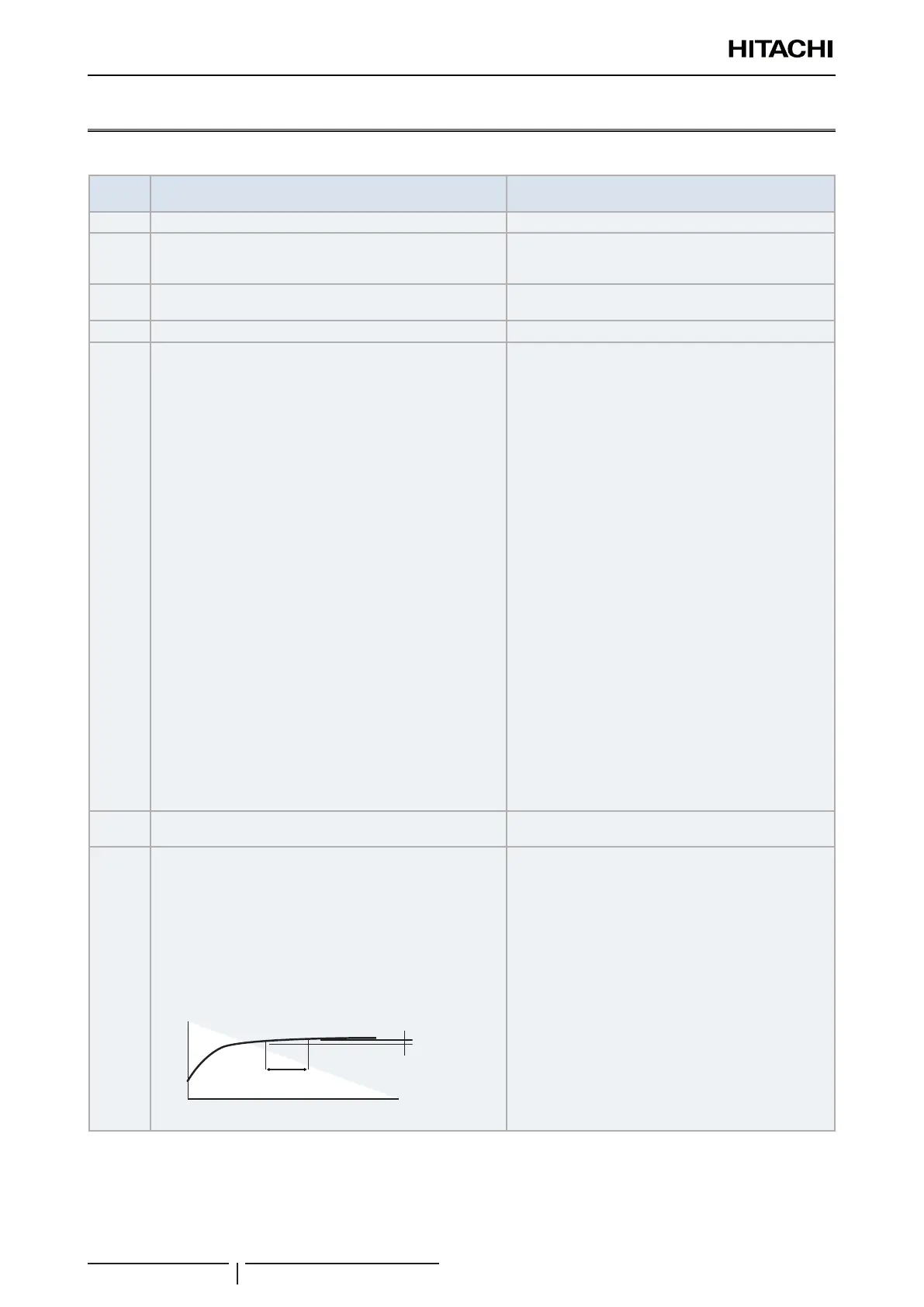
7
Check for a leakage of the check valve on the discharge gas
side:
• Enforced stoppage of the compressor → ON so that the
compressor will not run although the running command is
sent from the remote control switch.
• Check that variation of Ps on the outdoor unit PCB is
17 seconds. Make sure that the Ps increase is within
0.03 MPa in two minutes after the Ps increase at the
stoppage (during approximately ve minutes). Also make
sure that Pd > Ps.
0.03 MPa
or smaller
2 minutes
Time
Ps
When you stop the compressor for replacing:
• You can check the leakage of the check valve by
means of the Ps variation because the SVA opens
so that the discharge gas side of the inverter
compressor can connect to the low pressure side.
• 0.03 MPa/2 minutes is within the permissible limits
for the check valve on the discharge gas side.
• The leakage of the check valve may cause an
incorrect brazing due to the gas pressure at the
brazing of the discharge piping.
• If the compressor-replacing mode is performed again
set the DSW4-4 to OFF and keep the DSW4-4 at the
OFF side during ten minutes. Then start according to
the procedure No. 6.